background image

107-B00    Page 10/16 

f. 

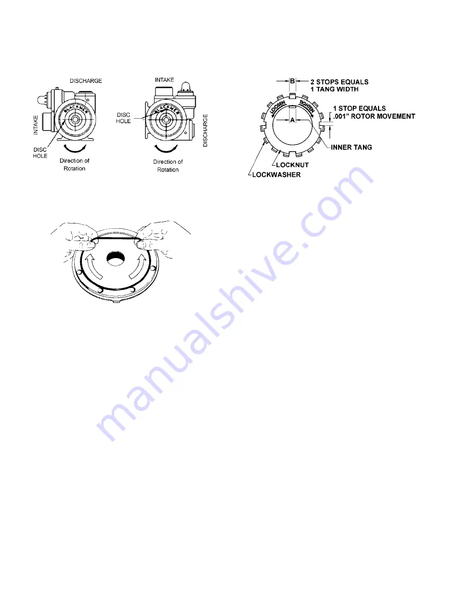
Position the disc relief hole so that when the head is 
mounted on the pump with the “Blackmer” name in 
an upright position, the disc hole will be towards the 
INTAKE side of the pump. See Figure 7. 

g. 

Install the disc machine screws (71A) and 
lockwashers (71B).


Figure 7 – Disc Relief Hole Location  (4-inch Models) 

10. Install a new head O-ring (72) in the groove on the inside 

face of the head. Lay the O-ring flat and start in on one 
side of the groove, stretching ahead with the fingers, as 
shown in Figure 7. 


Figure 7 – Head O-Ring Installation 


11. Carefully install the head assembly (20) over the shaft. 

Do not contact the end of the shaft with the mechanical 
seal. Position the head with the small weep hole towards 
the bottom of the pump. Install and partially tighten four 
head capscrews (21) 90° apart. The remaining capscrews 
will be installed in step 18. 

On 4-inch models, make sure the head is mounted with 
the “Blackmer” name upright and the disc relief hole 
towards the intake side of the pump. The seal jacket drive 
tangs must be engaged in the rotor slots. 

12. Hand pack the ball bearing (24) with grease. Refer to the 

"Lubrication" section for the recommended grease.  

13. Install the bearing into the head recess. The bearing balls 

should face outward, with the grease shield (ref. 123, 2” 
models only) inward. The bearing must be fully and 
squarely seated in the head. 

14. Turn the pump casing around and remove the outboard 

head and disc previously installed. 

15. Install the mechanical seal and disc in the outboard head 

as instructed in steps 7 through 8 for the 2 and 3-inch 
models or step 9 for the 4-inch models. 

16. Finish assembling the outboard side of the pump as 

instructed in steps 10 through 13. 

17. Rotate the shaft by hand to engage the mechanical seal 

drive tangs, and to test for binding or tight spots. If the 
rotor does not turn freely, lightly tap the rims of the heads 
with a soft faced mallet until the correct position is found. 

18. Install and partially tighten the remaining head capscrews 

19. Uniformly torque the head capscrews to 30 lbs ft (40.7 

Nm), alternating between one side of the head and the 
other. Frequently check that the shaft still turns freely. If 
tight, loosen the capscrews and repeat the procedure. If 
the shaft continues to bind, check for grease or dirt on the 
mechanical seal faces. 


Figure 8 – Locknut Assembly 

20. LOCKNUT ADJUSTMENT 

It is important that the bearing locknuts (24A) and 
lockwashers (24B) be installed and adjusted properly. 
Overtightening locknuts can cause bearing failure or a 
broken lockwasher tang. Loose locknuts will allow the 
rotor to shift against the discs, causing wear. See Fig. 8.


a.  On both ends of the pump shaft, install a lockwasher 

(24B) with the tangs facing outward, followed by a 
locknut (24A) with the tapered end inward. Ensure the 
inner tang "A" of the lockwasher is located in the slot 
in the shaft threads, bending it slightly, if necessary. 

b.  Tighten both locknuts to ensure that the bearings are 

bottomed in the head recess. DO NOT overtighten 
and bend or shear the lockwasher inner tang. 

c.  Loosen both locknuts one complete turn. 

d.  Tighten one locknut until a slight rotor drag is felt 

when turning the shaft by hand. 

e.  Back off the nut the width of one lockwasher tang "B".  

Secure the nut by bending the closest aligned 
lockwasher tang into the slot in the locknut. The pump 
should turn freely when rotated by hand. 

f.  Tighten the opposite locknut by hand until it is snug 

against the bearing. Then, using a spanner wrench, 
tighten the nut the width of one lockwasher tang “B”. 
Tighten just past the desired tang, then back off the 
nut to align the tang with the locknut slot. Secure the 
nut by bending the aligned lockwasher tang into the 
slot in the locknut. The pump should continue to turn 
freely when rotated by hand. 

g.  To check adjustment, grasp the nut and washer with 

fingers and rotate back and forth. If this cannot be 
done, one or both locknuts are too tight and should be 
alternately loosened one stop at a time 0.001" 
(0.025mm). Begin by loosening the locknut adjusted 
last. 

21. Inspect the grease seal (104) for wear or damage and 

replace as required. Grease the outside diameter of the 
grease seal and push it into the inboard bearing cover 
(27A) with the lip of the seal inward (towards the pump). 

22. Attach a new bearing cover gasket (26) and the inboard 

bearing cover (27A) to the inboard head. Install the 
outboard bearing cover (27) and a new gasket to the 
outboard head. Make sure the grease fittings (76) on the 
bearing covers are accessible. Install and torque the 
bearing cover capscrews (28) to 30 lbs ft (40.7 Nm). 

Summary of Contents for XLW2E-N

Page 1: ...r by contacting Blackmer Customer Service SAFETY DATA This is a SAFETY ALERT SYMBOL When you see this symbol on the product or in the manual look for one of the following signal words and be alert to the potential for personal injury death or major property damage Warns of hazards that WILL cause serious personal injury death or major property damage Warns of hazards that CAN cause serious persona...

Page 2: ...ace Hazardous pressure can cause personal injury or property damage PUMP DATA PUMP IDENTIFICATION A pump Identification tag containing the pump serial number I D number and model designation is attached to each pump It is recommended that the data from this tag be recorded and filed for future reference If replacement parts are needed or if information pertaining to the pump is required this data ...

Page 3: ...larly to avoid pump starvation 4 The intake system must be free of air leaks 5 Expansion joints placed at least 36 0 9m from the pump will compensate for expansion and contraction of the pipes Contact the flexible connector hose manufacturer for required maintenance care and design assistance in their use 6 Install pressure gauges in the NPT ports provided in the pump casing to check pump at start...

Page 4: ...ent is required The motor gearbox and pump are rigidly connected with bolted flange connections These flanges ensure the motor shaft gearbox shafts and pump shaft are aligned correctly without the need for manual alignment However due to variations in base and foundation geometry the unit will require shimming to reduce stress on the gearbox and pump adapter See PRESTART CHECKLIST section for deta...

Page 5: ... motor until it is unsupported 3d Try pulling out each of the shims while noticing the the pull tension 3e If the shims closest to the motor shaft easily pull out increase the shim thickness the same at all locations and recheck 3f If the shims furthest from the motor shaft easily pull out decrease the shim thickness the same at all locations and recheck 3g The unit is properly shimmed when all 4 ...

Page 6: ... LIMITED time at a reduced performance level FLUSHING THE PUMP NOTICE If flushing fluid is to be left in the pump for an extended time it must be a lubricating non corrosive fluid If a corrosive or non lubricating fluid is used it must be flushed from the pump immediately 1 To flush the pump run the pump with the discharge valve open and the intake valve closed Bleed air into the pump through the ...

Page 7: ...ause shock burns or death Hazardous voltage Can shock burn or cause death Failure to relieve system pressure prior to performing pump service or maintenance can cause personal injury or property damage Hazardous pressure can cause personal injury or property damage Disconnecting fluid or pressure containment components during pump operation can cause serious personal injury death or major property...

Page 8: ... Slide the lockwasher off the shaft Inspect the lockwasher for damage and replace as required c Repeat steps a and b on the opposite shaft end 6 Remove the head capscrews 21 Gently pry the head away from the casing using two large screwdrivers The head O ring should come off with the head assembly 7 Slide the head and O ring off the shaft The bearing 24 mechanical seal stationary seat and stationa...

Page 9: ... vanes and push rods are installed carefully insert the non driven end of rotor and shaft into the casing d Install the remaining vanes into the top positions of the rotor 7 DISC 2 and 3 inch Models Install the disc 71 on the inboard side of the pump with the seal cavity facing outward and the disc relief hole located as shown in Figure 6 Figure 6 Disc Relief Hole Location 2 and 3 inch Models 8 ME...

Page 10: ...ght loosen the capscrews and repeat the procedure If the shaft continues to bind check for grease or dirt on the mechanical seal faces Figure 8 Locknut Assembly 20 LOCKNUT ADJUSTMENT It is important that the bearing locknuts 24A and lockwashers 24B be installed and adjusted properly Overtightening locknuts can cause bearing failure or a broken lockwasher tang Loose locknuts will allow the rotor to...

Page 11: ...e spring guide 7 e After the relief valve has been adjusted tighten the Locknut 3 and install the relief valve cap 1 and O ring 88 NOTICE The relief valve setting MUST be tested and adjusted more precisely before putting the pump into service Refer to Relief Valve Setting and Adjustment Operation without guards in place can cause serious personal injury major property damage or death Do not operat...

Page 12: ...r and brake windings to verify the integrity of the winding insulation and inspect all terminal box openings and wire connection areas to verify that all components are dry and free of corrosion Long Term Storage By taking special precautions problems such as seal leakage and reducer failure due to the lack of lubrication improper lubrication quantity or contamination can be avoided The following ...

Page 13: ...alphaolefin Oil FG Food Grade Oil NOTICE The Ambient Temperature is intended to be an operation guideline based upon the typical properties of all the lubricant The viscosity and other properties of the lubricant change based upon load speed ambient conditions and reducer operating temperatures The user should consult with their lubrication supplier NORD gear before considering changes in oil type...

Page 14: ...nter the rotor and shaft between the heads Refer to Locknut Installation on Page 10 Contaminated mechanical seal faces Any trace of grease or dirt on the seal faces will prevent the faces from mating properly causing the rotor and shaft to bind or turn hard Use a tissue paper alcohol to clean the seal faces NOTE Apply a light oil or suitable lubricant to bronze seal faces only OTHER POSSIBLE CAUSE...

Page 15: ...y closed valves Excessive amount of elbows Suction lift too great Pump speed too high for the viscosity of the liquid being pumped Entrained air or vapors in the pump Check pipe joints for leakage of air Sometimes when recirculating liquid in a tank the returning liquid falling through the air carries air down into the tank which eventually gets back into the pump Pump speeds exceed the recommende...

Page 16: ...t Excessively worn vanes or vane slots Settled or solidified material in the pump at start up Overtightened V belts if used SEAL LEAKAGE Probable Cause O rings not compatible with the liquids pumped O rings nicked cut or twisted Shaft at seal area damaged worn or dirty Excessive cavitation Mechanical seal faces cracked scratched pitted or dirty Ball bearings overgreased MOTOR OVERLOAD Probable Cau...

Reviews: