


AODDAMPENER™
4
AODDampener automatic dampener models are designed specifically for use with air operated diaphragm pumps,
and are not recommended for use as Inlet Stabilizers at pump inlets or as Surge Suppressors at quick closing valves.
Use Inlet Stabilizer models on the inlet side of pumps and metal Surge Suppressors for water hammer or quick
closing valve applications. Consult factory for options.
ATEX models must be grounded (earthed) before operation.
Turn pump off and remove all pressure from system prior to dampener installation.
Remove all pressure from dampener AND pumping system before disassembly, removal or maintenance.
Equip dampener with constant source of clean compressed air.
DO NOT USE OXYGEN.
DO NOT exceed 150 psi (10.3 bar) maximum allowable working pressure (MAWP). Check maximum pressure rating
specified on dampener.
If missing, consult distributor or factory for specifications.
Always wear safety glasses and other appropriate safety equipment when installing, charging or repairing dampener.
Read and observe all safety warnings and instructions in this Manual before installation, operation or repair.
IMPORTANT! After maintenance or disassembly, use new fasteners and torque fasteners according to specification
on dampener tag.
If missing, consult distributor or factory for specifications.
Before performing a system pressure test, an air line with a constant source of compressed air must be attached to dampener
to avoid possible damage to diaphragms. Compressed air pressure must be equal to or greater
than system test pressure.
Installation & Operation Instructions: AODDAMPENER™ Models
DO NOT
use dampener if the fasteners (nuts and bolts) are corroded. Check for fastener corrosion frequently, especially in
atmospheres containing salt or corrosive chemicals, or if dampener leakage has occurred.
IMPORTANT!
After maintenance or disassembly, use new fasteners and torque fasteners according to specification on
dampener tag. If missing, consult distributor or factory for specifications.
Where dampeners are used in corrosive environments, nut and bolt fasteners should be regularly inspected and replaced with nut and
bolt fasteners of equal grade/strength value if corrosion is observed. Failure to conduct such regular inspections and replacement will
void the product warranty given by the manufacturer and the manufacturer will have no liability whatsoever for any vessel failure or
malfunction.
Step 1 — Installation Position
Install the dampener inline as close to the pump discharge as possible to absorb the pulse at its source and before any downstream
equipment such as risers, valves, elbows, meters or filters. Dampener installation should be no more than ten pipe diameters from
pump discharge. If using a flexible connector on the discharge side of the pump between the pump and system piping, the dampener
should be installed at the pump discharge manifold. The flexible connector should be attached to the dampener’s tee and system piping
(Figure 1). Since pressure is equal in all directions, the dampener can be installed in a vertical, horizontal or upside-down position. A
vertical installation is recommended for better drainage of the dampener. Limitations for horizontal and upside-down mounting include
high specific gravity, high viscosity, settling of solid material or possible air entrapment which could result in shortened diaphragm life
and/or reduced dampening performance. An isolation valve installed at the dampener inlet is suggested to assist in removal for repairs
(Figure 1).
Due to the nature of the material, PTFE diaphragm will
cold flow
. Prior to installation, tighten bolts to torque specification on
dampener tag.
Read Before Installation
Installation for Pump Discharge Pulsation
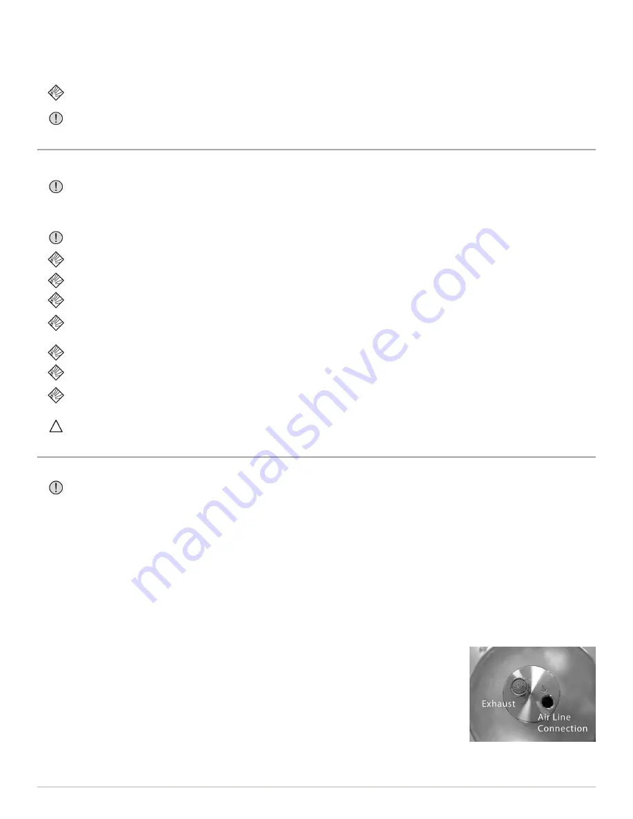
Step 2 — Air Line Connection
AODDampener models have an automatic valve with two NPT ports fitted in the non-wetted housing.
Supply compressed air to the dampener using a 1/4” or larger air line to ensure adequate air supply
to the dampener. Using a suitable adapter, connect the air line to the NPT inlet connection indicated
by the arrow. Attach the air line to the existing pump air supply line before any regulator used at
the pump’s air valve (Figure 1). The compressed air pressure to the dampener must be equal to or
greater than the air pressure supplied to the pump.
Compressed air should be applied to the dampener charge port at all times for proper operation. In
case the compressed air supply to the dampener is interrupted, it is recommended that a check valve
be added to the compressed air supply line to prevent the charge from escaping through the air inlet
while the dampener is depressurized.


