background image

AODDAMPENER™

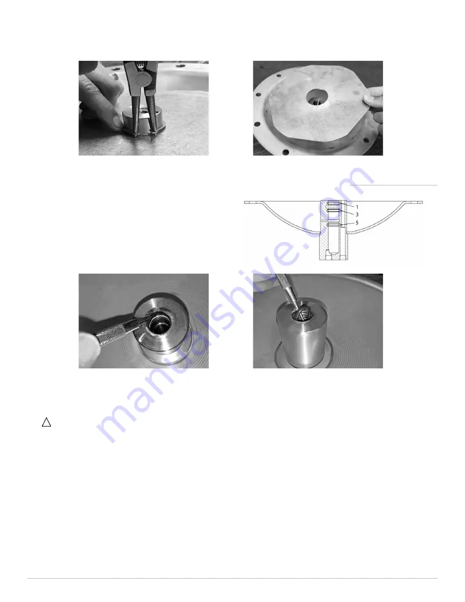
4.  Apply a thin coat of lubricant (such as Molycote® 55 or equivalent) to new O-rings and install in grooves 5, 3 and 1 in that order 

(Figure 2). The automatic valve will not operate if O-rings are installed in the wrong grooves.

Figure 2

O-Ring Replacement

1.  There are five grooves in the automatic valve with O-ring 

seals installed in grooves 1, 3 and 5 (Figure 2). O-rings in 

the automatic valve should be replaced with each diaphragm 

replacement. New O-rings are included in Diaphragm 

Replacement Kits.

2.  Secure the dampener non-wetted housing into a vise with soft 

jaws with the inside (interior) of the housing facing up. 

3.  Using an O-ring pick, remove old O-rings from the automatic 

valve and discard.

Install O-Rings 

with

 O-Ring Installation Tool:

It is highly recommended that the AODDampener O-Ring Installation Tool be used to install O-rings in the automatic valve to 

ensure proper placement on reassembly. The tool is engineered to properly install O-rings one at time in the correct position 

and is available in three sizes to fit 1” inlet models, 1.5 and 2” inlet models, and 3” inlet models. Refer to 

Replacement Kits 

and Tools

 above.

a.  Using the appropriate size O-Ring Installation Tool, insert the O-ring tool slide into the body of the tool until O-ring grooves align.
b.  Position the first O-ring into the first groove on the tool to install the O-ring in groove 5 of the automatic valve. Use your finger to 

cover the top of slide to prevent the O-ring from slipping out of place and push the slide forward to properly position the O-ring 

on the tool.

c.  With the slide held in place, insert the tool into the automatic valve until the shoulder of the tool is flush with the top of the valve. 

Hold the tool in place and carefully remove the slide from the tool body. Remove the entire tool from the automatic valve and 

confirm the O-ring is properly seated in groove 5.

d.  Reinsert the O-ring tool slide into the body of the tool until O-ring grooves align and repeat steps above to install the two 

remaining O-rings. Use the second groove on the tool to install the second O-ring in groove 3 of the automatic valve, and the 

third groove on the tool to install the third O-ring in groove 1 of the automatic valve.

8.  AODDampener models are equipped with a backup plate attached to the non-wetted housing to minimize damage to the 

diaphragm if the dampener loses charge. The backup plate is held in place by two retaining rings. It is not necessary to remove the 

backup plate during disassembly, except when necessary to clean any oil residue or remove debris from the non-wetted housing. 

To remove the backup plate, remove the retaining ring using snap ring pliers and lift the backup plate off the housing.

Summary of Contents for AODDampener

Page 1: ...g system maximizing the reduction in pulsation When sized correctly and properly installed the AODDampener will greatly reduce the damaging effects of pressure variations and improve the efficiency of transferring fluids All dampeners manufactured by BLACOH use pressure bodies made in the USA to ensure quality Prior to shipment each and every dampener is factory pressure tested to assure proper fu...

Page 2: ... Fluid Controls Inc Model No Serial No Pump Area and Number Purchased From Contact Phone Email Installation Date MODEL Specifications Installation Information Table of Contents SAFETY Warnings 2 Safety Symbols 2 General Safety 2 Equipment Misuse Hazard 2 GENERAL Information 3 Must Read Before Installation 3 Installation Notes 3 ATEX Standard 3 Temperature Limits 3 Maintenance 3 Installation Operat...

Page 3: ...ain internal fluid air or gas pressure DO NOT pump incompatible fluids through dampener Consult distributor or factory if you are not sure of the compatibility of system fluids with dampener materials AODDampener models are designed to operate with compressed air only Other compressed gases have not been tested and may be unsafe to use DO NOT USE OXYGEN Always shut off air supply remove internal d...

Page 4: ...Standard Dampening of flow pulsations can only be effective if a minimum of 5 to 10 psi 0 4 to 0 7 bar back pressure downstream of dampener is available A Blacoh back pressure valve may be required downstream of dampener except when dampener is used as an inlet stabilizer for the inlet side of the pump It is recommended that a Blacoh pressure relief valve be installed in all pump systems to ensure...

Page 5: ...o conduct such regular inspections and replacement will void the product warranty given by the manufacturer and the manufacturer will have no liability whatsoever for any vessel failure or malfunction Step 1 Installation Position Install the dampener inline as close to the pump discharge as possible to absorb the pulse at its source and before any downstream equipment such as risers valves elbows ...

Page 6: ... dampener is fully functional and will operate automatically when the pump is started To avoid damage to diaphragms DO NOT start the pump before compressed air is supplied to dampener Step 3 Startup If a diaphragm failure occurs it is possible for the pumped product to enter the dampener air chamber and be expelled from the dampener exhaust It is recommended that the exhaust be plumbed to a safe a...

Page 7: ...and bolts Process liquid may be present if diaphragm failure has occurred Always wear safety glasses and other appropriate safety equipment when disassembling dampener 6 The backup diaphragm is attached to the air control shaft Gently pull down on the diaphragm to slide the shaft out from the automatic valve in the non wetted housing If the shaft does not slide out easily remove the muffler insert...

Page 8: ...until O ring grooves align b Position the first O ring into the first groove on the tool to install the O ring in groove 5 of the automatic valve Use your finger to cover the top of slide to prevent the O ring from slipping out of place and push the slide forward to properly position the O ring on the tool c With the slide held in place insert the tool into the automatic valve until the shoulder o...

Page 9: ...o the shaft with two hands and stop when hand tight Remove the diaphragm and shaft from the vise and insert the shaft into the automatic valve Reassembly 1 If removed on disassembly reinstall the backup plate Clean and dry the internal housing surface taking particular care to ensure the flange area is completely clean and dry Slide the backup plate onto the non wetted housing until it rests on th...

Page 10: ...holes aligned Ensure the diaphragms fit together snugly to minimize any air between them 6 Insert bolts with flat washers through the top side Attach flat washers and lock nuts on the bottom side for each bolt Lubricate bolt threads with anti seize compound or oil before installing nuts to prevent galling 7 Torque bolts in a star pattern according to the following torque specifications AOD 10 1 in...

Page 11: ...ed Housing 2 Non wetted Housing 3 Bolt 4 Washer 5 Nut 6 PTFE Diaphragm 7 Backup Diaphragm 8 Air Control Shaft 9 O Ring 10 Backup Plate 11 Retaining Ring 12 Plug 13 Muffler 14 Automatic Valve 13 3 4 2 12 10 11 9 8 7 6 1 4 5 14 Exploded View ...

Page 12: ... available on Blacoh s website at www Blacoh com M26E11_030 Manufacturer s Limited Warranty Return Policy PROUDLY MANUFACTURED IN THE USA Blacoh Headquarters 601 Columbia Ave Bldg D Riverside CA 92507 USA 951 342 3100 www Blacoh com Sales Blacoh com ...

Reviews: