16
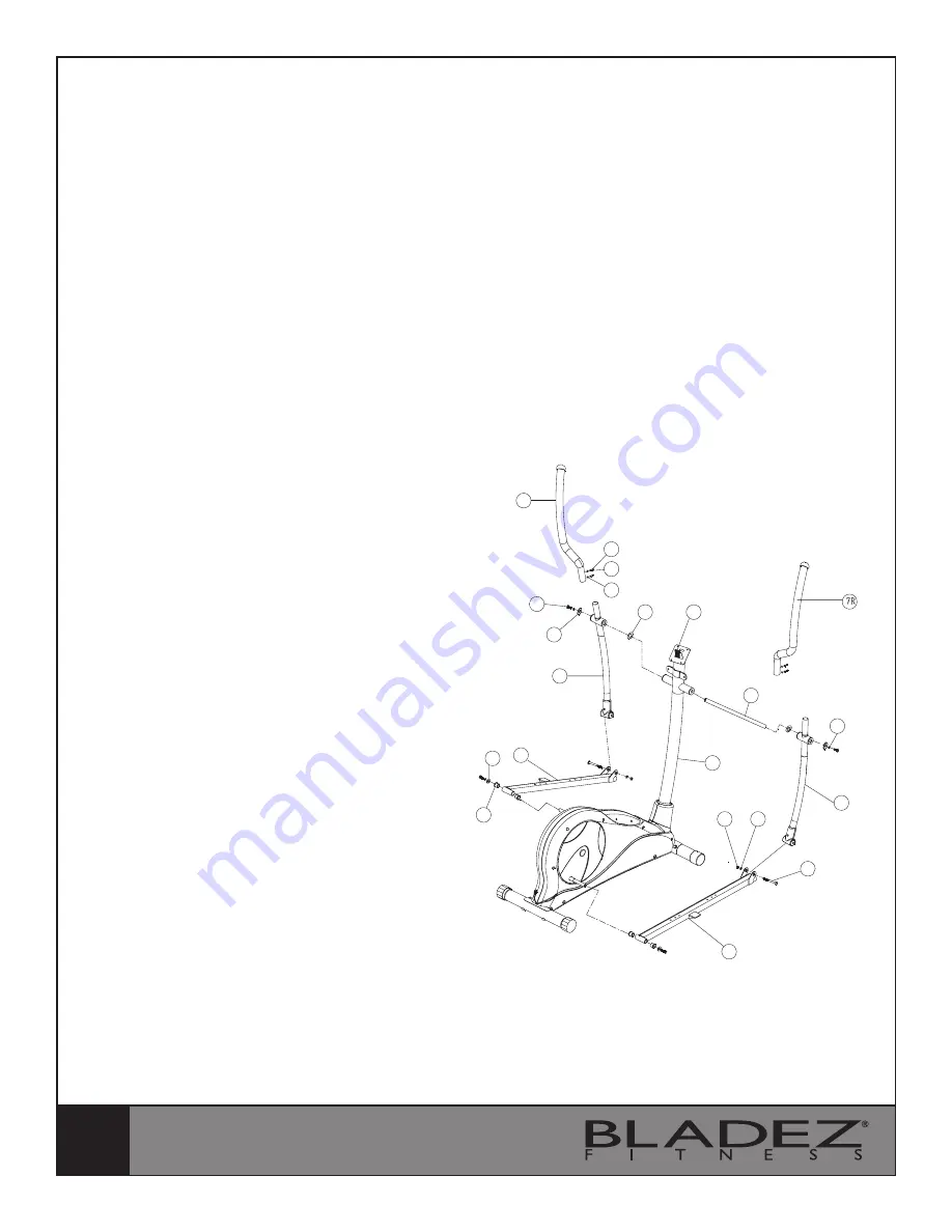
STEP 3
I. Place the rotation rod (74) into the
Handlebar Post (73). Attach the Upper
Handlebars (7L & 7R) onto the Lower
Handlebars (13L & 13R) using 2×M8
Allen Bolts (72), 2×M8 Spring Washers
(11) and 2×Curved Washers (71) for
each Handlebar. Slide the left and right
Handlebars onto the Rotation Rod (74)
and secure in place with Flat Washer (5),
M8.5 Flat Washer (12), Spring Washer
(11) and Allen Bolt (10) for each side.
II. Attach the Footplate Bars (26L &
26R) by sliding them onto the Crank
plate bushings and securing in place
with M8 Anti-Loose Allen Bolts (10),
M8 Spring Washer (11) and M8 Flat
Washer (28) for each side. Tighten
fully. Align and slip the Footplate Bars
(26L& 26R) into the Lower Handlebars
(13L & 13R) and attach together with
2×M10 Allen Bolts (17), 2×Flat Washers
(22) and 2×M10 Nylon Locknuts (19).
Tighten fully.
7L
10
12
13L
26L
28
72
11
71
27
17
13R
22
19
73
26R
70
74
5
11
Summary of Contents for METRON GS
Page 13: ...13 HARDWARE PACKAGE PART 79...


