3
AMA 299
Part N
o
: 9859.8x
QAM Modulator
ASI-TS
→
DVB-C/ ITU-T J.83 Annex B, C
A
LINE
1. Safety and operating instructions
When assembling, starting-up and adjusting the modules, it is necessary to consider the system specific references in
the manual instruction.
The modules may only be installed and started up by authorized technical personne.
When assembling the modules into the receiving points, the adherence of the EMC regulations is to be secured.
The assembly and wiring have to be done without voltage.
With all work the defaults of the DIN EN 50083 have to be considered. Especially the safety relevant execution of the
DIN EN 60728-11 [3] is necessary.
The devices come under protection classification I. It is absolutely necessary, therefore, to insert the mains plug into a
socket with protective contact.
2. Device variants
AMA 299
9859.81 ASI - TS
→
DVB-C / ITU-T J.83 Annex B, C
9859.82 ASI - TS
→
IFI
→
DVB-C / ITU-T J.83 Annex B, C
3. General
The QAM Modulator AMA 299 is a module of the head end system A-LINE which is conceived as a complete system for big and
middle-sized networks.The module converts one digital transponder into the digital cable standard DVB-C, ITU-T J.83 Annex B or C.
The signal will be transcoded from the ASI transport stream into cable TV channels.
The status of the assembly will displayed with LED‘s (see section 5.2 ”Meaning of the LED signals”).
4. Functional description
The data stream which results from the ASI input is passed to a FIFO. All services of the resulting transport stream which shall be
processed into the QAM modulator will be choosen by controling software of the module. The SI and PSI tables affected (i.e. the PAT,
PMT, SDT, EIT, NIT) are automatically corrected. The changed SI an PSI tables are fed into the QAM modulator and an IF signal is ge-
nerated at the output channel. There is a free choise of frequency in the output channel from 45 to 862 MHz. On the output side, the
modulator does not leak to adjacent channels. For level error reporting a reference level is generated internally and is compared with
current value permanently. After each programming of the level and/or frequency values an automatic measurement of the reference
level takes place. The integrated management unit consists of the data interface for PC/ LAN/ WAN (IP/ Ethernet interface / RJ 45).
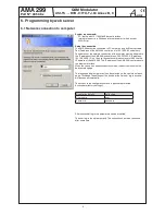
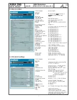
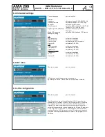
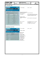
The management of the module can be done via PC/Laptop (see programming).
The IP address of each device can be edited and adjusted to the respective LAN.
WEEE-Reg.-Nr. DE 50389067


