background image

11

AMB 307

Part N

o

: 9730.01

COFDM Modulator

ASI-TS 

 DVB-T (COFDM)

B

LINE

Item

Message

Message type

Explanation

17

Up Converter: PLL1 not locked

CRITICAL

no funktion at the PLL 1 converter

18

Up Converter: PLL2 not locked

CRITICAL

no funktion at the PLL 2 converter

19

Up Converter: IF input too small

WARNING

IF input too small at the Up converter

20

Up Converter: IF input too large

WARNING

IF input too large at the Up converter

21

Up Converter: RF output too small

WARNING

RF output too small at the Up converter

22

Up Converter: RF output too large

WARNING

RF output too large at the Up converter

23

Up Converter ok

INFORMATION

Up converter works correctly

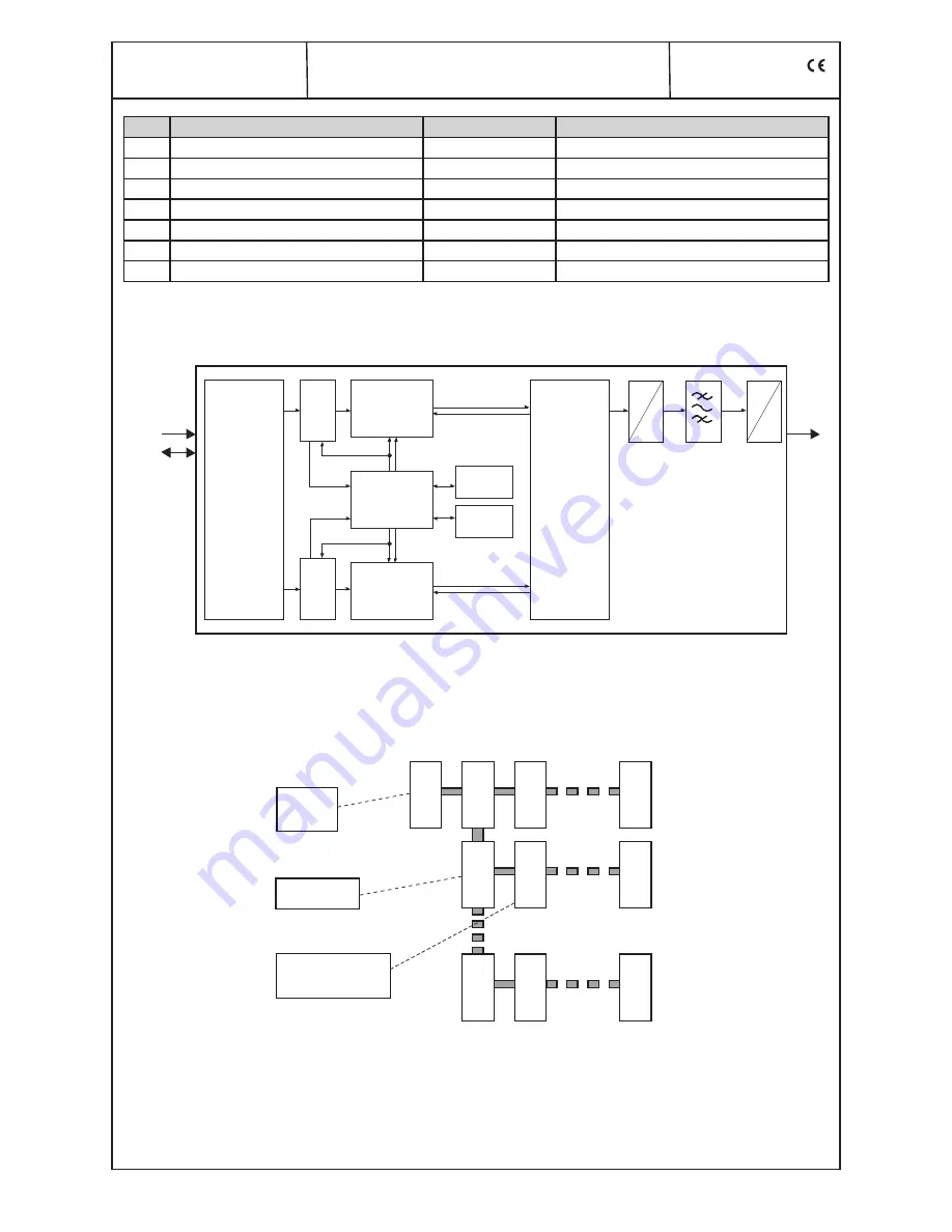
11. Block diagram

12. Head end bus structure

ASI

frontend

PID

filter

PID

filter

multiplexer

with

PCR correct.

multiplexer

with

PCR correct.

SI/ PSI

processor

flash

SDRAM

COFDM

modulator

BP

 IF


RF


 D


A

TS

TS

TS

TS

TS

TS

CTRL

CTRL

SI/ PSI 
data

SI/ PSI 
data

clock

RF

ASI

clock

HCB x00

Headend
Controller

BEB x00

Bus  Extender

Module

signal processing 
unit

H

C

B

 x

00

M

od

ul

e

A

D

D

R

. 1

5

B

E

B

 x

00

A

D

D

R

. 0

1

B

E

B

 x

00

A

D

D

R

. 0

2

B

E

B

 x

00

A

D

D

R

. 1

5

M

od

ul

e

A

D

D

R

. 0

1

M

od

ul

A

D

D

R

. 0

1

M

od

ul

e

A

D

D

R

. 0

1

M

od

ul

e

A

D

D

R

. 1

5

M

od

ul

e

A

D

D

R

. 1

5

The number of the possible module connections (01 ... 15) to a 
BEB x00 depends on the total power consumption of this line!

Summary of Contents for AMB 307

Page 1: ...tus LED s 4 8 Programming by web server 5 8 1 Main menu 5 8 2 Extended settings 6 8 3 NIT entries 6 8 4 Program filter 6 8 5 Data rate overview 6 8 6 Table processing 7 8 7 Configuration channel list...

Page 2: ...cal data With all work the defaults of the DIN EN 50083 have to be considered Especially the safety relevant execution of the DIN EN 60728 11 2 is necessary 2 Device variants AMB 307 9730 01 ASI TS DV...

Page 3: ...ming mode on each module by selecting the line BEB x00 and the module position 01 15 at the Headend Controller HCB x00 yellow LED illuminates until the beginning of the parameter adjustment Adjustment...

Page 4: ...eaning of LED signals 7 1 LED s for the ASI ports Colour Status Meaning of display green permanently on ASI channel has been configured as input flashing no ASI signal yellow permanently on ASI channe...

Page 5: ...Hz Guard intervall selection 1 32 1 16 1 8 1 4 Code rate selection 1 2 2 3 3 4 5 6 7 8 Status Operating mode COFDM Modulator according adjustment menu 1 Hierarchical modulation according adjustment me...

Page 6: ...e item number module address in head end Program filter configuration Filter function selection On Off Other transporder information pass or drop of additional informations e g electronic program guid...

Page 7: ...nge 0 65535 Transport stream Change TS Identific selection On Off Transport stream ID adjustment range 0 65535 Network ID adjustment range 0 65535 8 7 Configuration channel list LCN menu 6 Name of dev...

Page 8: ...COFDM BLINE 8 8 Software overview menu 7 Name of device item number module address in head end Software version Controller of terminals board FPGA Bootcontroller COFDM modulator TS Mux FPGA TS manage...

Page 9: ...memory error memory up converter Original TS ID s display transport stream ID and network ID Information Temperature Temperature of terminals board Device number display of the device number Device in...

Page 10: ...12 FPGA TS Packed buffer overflow WARNING overflow of TS packet buffer 13 Data overflow CRITICAL overflow of data 14 Sync error data FIFO CRITICAL data FIFO doesn t work correctly 15 No response to OP...

Page 11: ...put too large WARNING RF output too large at the Up converter 23 Up Converter ok INFORMATION Up converter works correctly 11 Block diagram 12 Head end bus structure ASI frontend PID filter PID filter...

Page 12: ...Max output level 115 dB V Level adjustment range 0 31 5 dB 0 5 dB steps Channel allocation adjacent channel ability Connector F socket Impedance 75 Return loss 18 dB 45 MHz 1 5 dB Octave Signal quali...

Page 13: ...ntifier PMT Program Map Table PSI Program Service Information QAM Quadrature Amplitude Modulation QPSK Quadrature Phase Shift Keying RF Radio Frequency SDT Service Description Table SI Service Informa...

Page 14: ...herewith declares the conformity of the product Product name COFDM Modulator Type AMB 307 Product number 9730 01 according to the following regulations EN 50083 2 EN 60728 11 as far as relevant and ad...

Reviews: