23
EMA x08/407
Part N
o
: 917x.xx
ENCODER/ MULTIPLEXER
SDI/ A/V
→
ASI(TS) & IP(TS)
HDMI
→
ASI(TS) & IP(TS)
A
LINE
Note:
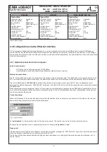
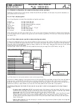
The SID/ PID for the slots configured (the programs and channels) is automatically allocated according to a fixed pattern. Inserting de-
tails of the device in the cascade and the number of the cascade ensures that the values will not overlap. If “outside” transport streams
are being processed at the ASI input port, care must be taken to ensure that if the SID/ PIDs of any external and internal program
streams overlap, the internal program streams have priority. Any “external” program streams with the same names will be blocked at a
filter and not fed into the output port.
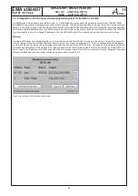
Operating several cascades within a network (a head end)
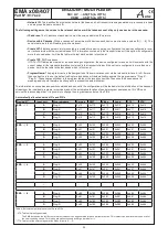
To get unique service ID‘s if there are several cascades in one head end, an offset is automatically added for the parameter “cascade
number within network” (CN
o
):
Cascade N
o
1
2
3
4
5
6
7
8
Offset
0x00
0x04
0x08
0x0C
0x80
0x84
0x88
0x8C
Table 5: Offset for the service ID‘s if several cascades are operated in a network
3.3.5 Transport stream bit rate (TS out bit rate), system bit rate
The transport stream bit rate at the ASI output port can be set in the range between 1,024 kbps and 214 Mbps with steps of 1 kbps.
The output bit rate can be selected independently of the input bit rate at the ASI input port. However, care must be taken to ensure that
the entire volume of data is transmitted, including the DVB channels generated additionally by the EMA device. It should be noted that
the transport stream at the ASI input may contain components with a fluctuating data rate. When estimating the bandwidth which will be
necessary for the transmission of newly generated programs, this should be borne in mind.
The bit rate (“TS-Out bit rate”) is selected in the configuration settings under “Channel Mux“.
For the EMA device, the maximum “TS Out Bit Rate“ possible is 214 Mbps. When deciding the “TS Out Bit Rate“ it is necessary
and important to check what is the maximum transport stream bit rate which can be processed or forwarded by succeeding
components such as modulators and upconverters.
The bandwidth (bit rate) which is available can be distributed across the channels generated by the EMA device in any proportions de-
sired. The more channels are transmitted, the lower is the available system bit rate (slot bandwidth) for each channel. Whenever indivi-
dual settings are made, care should be taken to ensure that the figures entered into the configuration mask make sense.
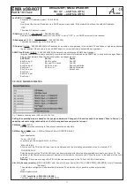
Configuration of the system bit rates and “TS-Out Bit Rate”, the output bit rate
When delivered and if reset is carried out with firmware, the system bit rates (slot bandwidth) of each channel will be set to 6 Mbps. This
setting should be seen simply as an upper limit and can be varied according to the content of the data being transmitted. It is possible
to adjust the figures for each channel according to need. The “TS-Out Bit Rate”, which is the data output rate, is preset to 38 Mbps,
which gives enough scope for reliable operation as long as the “ASI Main IN”, the input port, is deactivated. The output rate must be
decided in relation to the content being added, with a safety margin of at least 10 per cent, since it is not possible definitely to exclude
swings in the data rate taking it over the upper limit.
Examples of estimation of the “TS-Out Bit Rate”, the output bit rate
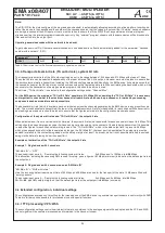
Example 1: Single device with 4 encoders
“ASI Main IN“ = “OFF“
The encoder input ports A ... D employ the following system bit rates:
3x 6 Mbps and 1x 10 Mbps, total
28
Mbps
This allocation, including the necessary
10%
reserve for safety, gives a figure of
31
Mbps (minimum) to be set as the data output rate at
the output port.
Example 2: Single device with 4 encoders and an “ASI Main IN“
“ASI Main IN“ = “MUX with intern“
Here the incoming data stream has a bit rate of 50 Mbps, and 36 Mbps are used for the transport of the data. 14 Mbps are filled with
“empty packets”.
The encoder input ports A ... D employ the following system bit rates:
2x 4 Mbps and 2x 8 Mbps, total
24
Mbps
36+24=
60
, plus
10%
safety margin, so that the data output rate at the output port is
66
Mbps (minimum).
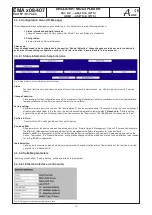
3.4 Extended configuration, individual settings
The configurations explained so far suffice for the intended use of the EMA device to generate transport streams in conformity with DVB.
There are further options possible for professional use with special functions.
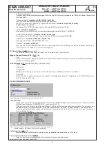
3.4.1 TTX processing/ VPS/ WSS
These configuration settings control how teletext information contained in the analogue signal will be adopted and the VPS and WSS
control signals will be captured, processed and forwarded in the transport stream.

