background image

BLANKOM IRD-6100      HD IRD User Manual 


BLANKOM_IRD-6100_User_Manual_RR-V1.1-03-2018.doc   

- 28 - 


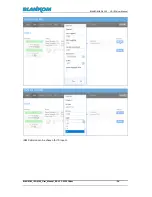
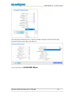
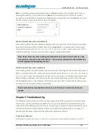
After changing the Decoder Input, you need to check GET and maybe Auto Search and Finger 
Switch to re-load the Input device into this menu: 


Cross connection to the 

CAM-CARD-Menu:


Summary of Contents for IRD-6100

Page 1: ...BLANKOM IRD 6100 HD IRD User Manual...

Page 2: ...Connection 10 Signal Cable Connection 11 IRD 6100 HD IRD Satellite Receiver Signal Cable Connections 11 Chapter 3 Operation 13 Keypad Function Description 13 Main Interface 14 General Setting 14 Input...

Page 3: ...tion 23 Login Interface 23 Main Interface 23 System config 25 General Settings for the DECODER Output values 26 MPTS Output 29 MUX Mode 30 SPTS Outputs 32 Transmit 34 Now we crosscheck what we are get...

Page 4: ...to use an optional ASI output interface which can pass through the Frontend Input TS directly Optional available with modules for DVB T 2 SFN network 10MHz Sync MIP Statement Text and pictures herein...

Page 5: ...User_Manual_RR V1 1 03 2018 doc 5 Application Example Of course instead of the HDMI Encoder a usage of the HD SDI encoder SDE 264 265 is possible too IP MPTS Inputs can be used as well as ASI Inputs t...

Page 6: ...ymbol rate QPSK 1 45Mbauds 8PSK 2 30Mbauds 4 DMB T 146MHz 862 MHz 6 7 8 MHz bandwidth 5 DVB T 146MHz 862 MHz 6 7 8 MHz bandwidth 6 ISDB T 153 MHz 862 MHz 6 7 8 MHz bandwidth 7 ATSC T 54MHz 858MHz 6MHz...

Page 7: ...HD SD SDI BNC 1080i 25 29 97 30fps 720p 50 59 94fps 576i 25fps 480i 29 97fps 1x HDMI 1080i 25 29 97 30fps 720p 50 59 94fps Audio Output Stereo unbalanced audio BNC interface Stereo balanced audio XLR...

Page 8: ...onitor 8 Switch Button 9 PCMCIA CAM interface Rear Panel Illustration 1 Loop Out Interface F connector 2 RF IN Interface F connector 3 IP IN OUT Interface RJ45 FE is working GE is not in use 4 ASI IN...

Page 9: ...nstall device please follow the below steps The details of installation will be described at the rest part of this chapter Users can also refer rear panel chart during the installation The main conten...

Page 10: ...ossible Users should make sure the 2 ends of grounding wire well electric conducted and be antirust It is prohibited to use any other device as part of grounding electric circuit The area of the condu...

Page 11: ...and LOOP OUT Connection The User can find the RF IN and LOOP OUT interface on the device according to the connectors marked and described on the rear panel illustration and connect the right cables O...

Page 12: ...ders and multiplexers Component Output CVBS and Audio Output Connection The User can connect the YPbPr CVBS and Left Right sound channel interfaces on the device according to the connectors described...

Page 13: ...nected to i e an IP encoder or a studio mixing device amplifier Chapter 3 Operation The front panel of the BLANKOM IRD 6100 HD IRD is one of the user operating interfaces and the equipment can be conv...

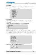
Page 14: ...1 to 1 3 represents the tuner ASI and IP input ports of the IRD User can multiplex the input programs from any port to output any program or all the programs at the same time By pressing the Enter ke...

Page 15: ...in its corresponding submenu 1 1 2 1 1 3 1 1 4 1 1 5 At the submenu 1 1 6 user can decide whether to turn on off the 22 KHZ Switch ASI IN By pressing the Enter key to enter into the submenu of 1 2 1...

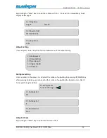
Page 16: ...2 1 and select the modes of outputting By pressing UP DOWN key after pressing Enter key user can see the four modes of outputting the Signals in turn ASI IP Tuner passthrough and Mux Output Bit rate B...

Page 17: ...tput IP address output port and decide whether to output the signals from IP port Decoder Setting User can press Enter key to enter into below menu of the decoder setting and execute video setting aud...

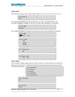
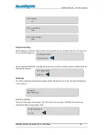
Page 18: ...after entering into above menu user can see all the options of standard Audio Setting User can enter into below submenu by pressing the Enter key Then select the audio choose the ES mode consists of s...

Page 19: ...programs will be displayed individually as below Searching The device will start searching the programs automatically after user select the mode of decoding in the menu 3 5 Decoder Selecting There are...

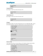
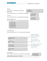
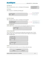
Page 20: ...Setting User can press Enter key to enter into below menu of the network setting IP Address After entering into the menu 5 1 it will display the following page Subnet Mask After entering into the menu...

Page 21: ...e following page SPTS IP Address After entering into the menu of 5 6 2 it will display the following page 5 3 Gateway 192 168 002 001 5 4 MAC Address 201205071337 5 5 Service IP 192 168 003 137 5 6 1...

Page 22: ...estore the device into the last saved configuration by choosing the menu 7 1 Saved Config and also user can restore the device into factory default configuration by choosing the menu 7 2 Default Confi...

Page 23: ...and give a user prompt to input user name and password The default user name is admin and password is admin User can add users and passwords as needed Details please refer to below other Settings The...

Page 24: ...BLANKOM IRD 6100 HD IRD User Manual BLANKOM_IRD 6100_User_Manual_RR V1 1 03 2018 doc 24 IGMP Version can be chosen for IP Inputs...

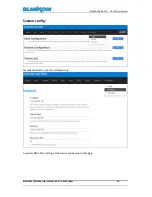
Page 25: ...OM IRD 6100 HD IRD User Manual BLANKOM_IRD 6100_User_Manual_RR V1 1 03 2018 doc 25 System config Save Restore Factory set are selfexplaining As well as NMS Port settings of the device and password cha...

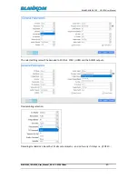
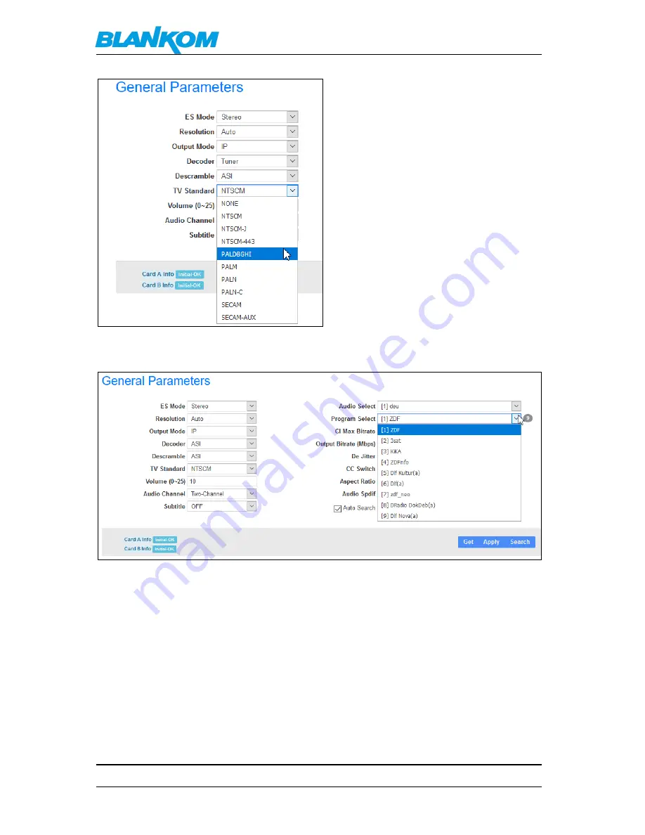
Page 26: ...018 doc 26 General Settings for the DECODER Output values First of all the user should understand that the Decoder parameters and other functions like i e MUX depending from each other See above scree...

Page 27: ...OM_IRD 6100_User_Manual_RR V1 1 03 2018 doc 27 The selected Program will be decoded to SDI Out YPbPr HDMI and the AUDIO outputs Descrambling selection Decoding standard can be set but its almost autom...

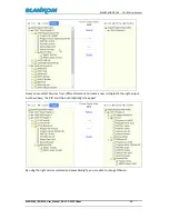
Page 28: ...ual BLANKOM_IRD 6100_User_Manual_RR V1 1 03 2018 doc 28 After changing the Decoder Input you need to check GET and maybe Auto Search and Finger Switch to re load the Input device into this menu Cross...

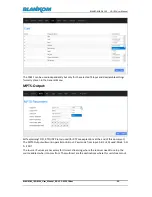
Page 29: ...neral Menu MPTS Output Self explaining OFF RTP UDP Protocl used for RTP see explantions at the end of this document The MPTS Output will work in parallel on ASI out Pass mode from Input ASI 2 4 Muxed...

Page 30: ...Manual_RR V1 1 03 2018 doc 30 MUX Mode Prior to use the mux mode you must enable it in the General settings You will start with the input source which are shown but empty So you need to select each an...

Page 31: ...l_RR V1 1 03 2018 doc 31 Now you can select Services from differentsources and create a new multiplex to the right output As shown here the PID s will be automatically remapped By using the right serv...

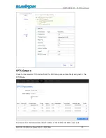
Page 32: ...M_IRD 6100_User_Manual_RR V1 1 03 2018 doc 32 SPTS Outputs These former selected TV Services from the MUX setup are automatically assigned to the SPTS Menu The Source IP ist the Network interface IP A...

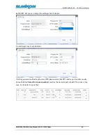
Page 33: ...u can change the settings of each stream Do not forget to set a valid bitrate If setting up same multicast address and RTP please assure that RTP needs a port number usually above 5004 and it must be...

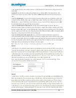
Page 34: ...s there are certain PID s which don t belong to any program but the user might want to pass them through the multiplexing module without any data missing or changing This is the main purpose of this f...

Page 35: ...NKOM_IRD 6100_User_Manual_RR V1 1 03 2018 doc 35 ASI 3 4 PASSTHROUGH IP Streams SPTS Visually checked the HDMI Out with a TV Set tagesschau24HD comes out HD SDI output should be there as well Before c...

Page 36: ...al_RR V1 1 03 2018 doc 36 It s the muxed output as MPTS and we have PID 12hex as well as PID 12 130 but this is unknown actually because standardised EIT PID x12 has been remapped to a free PID so rec...

Page 37: ...BISS E uses the same scrambling algorithm as BISS Mode 1 but that there is an additional encryption on the session word BISS Mode 1 uses a 12 digit hexadecimal key as session word The session word ha...

Page 38: ...get the injected ID of the IRD s and use this together with a session word to get calculated the encrypted session word using the DES3 algorithm Communicate the ESW to the receive site s More details...

Page 39: ...B C D E and F Under this mode SK cannot be input in the column as the data which works with ESW has been embedded inside the device after users select Burned Key which refers that users choose Device...

Page 40: ...r cord Power cord or socket damaged Any liquid flowed into device Any stuff causes circuit short Device in damp environment Device was suffered from physical damage Longtime idle After switching on an...

Page 41: ...are listed below The range of addresses between 224 0 0 0 and 224 0 0 255 inclusive is reserved for the use of routing protocols and other low level topology discovery or maintenance protocols such a...

Page 42: ...different UDP port numbers as well This is because a server and all software running on the server receives ALL multicast traffic on an open port and extra processing is required to filter out the re...

Page 43: ...2008 use the IANA range by default 5 Windows Server 2003 uses the range 1025 5000 by default until Microsoft security update MS08 037 from 2008 is installed after which it uses the IANA range by defa...

Page 44: ...um field may be used for error checking of the header and data This field is optional in IPv4 and mandatory in IPv6 6 The field carries all zeros if unused 7 RTP a part from https tools ietf org html...

Page 45: ...ng SAP Session Announcement Protocol IPv4 global scope sessions use multicast addresses in the range 224 2 128 0 224 2 255 255 with SAP Announcements being sent to 224 2 127 254 Port 9875 note that 22...

Reviews: