3
STR 821
Part N
o
: 9085.01
SAT-AUDIO Transmodulator
2 x DVB-S (QPSK)
→
6 x FM
B
LINE
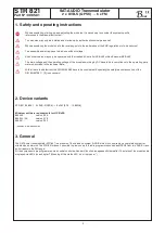
The manual instructions of the Headend Controller HCB x00 and the Bus Extender BEB x00 have to be considered!
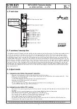
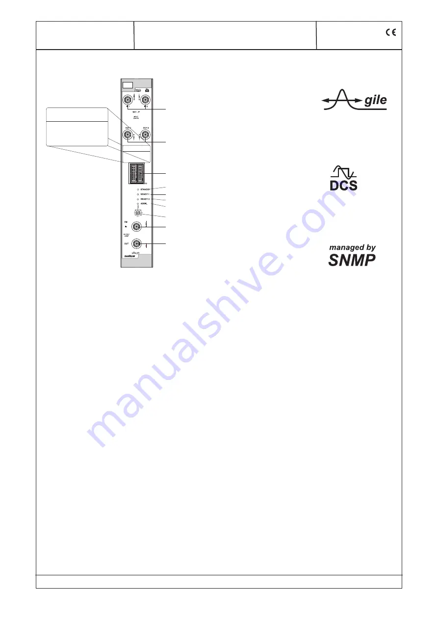
4. Front view
5. Functional description
The transport streams (TS) passed on by the input section are processed on entering the system. The SI data are extracted and sent
on to the control system so that the services to be decoded can be displayed and selected. At the same time, the audio streams
to be decoded are filtered out of the transport streams, as are the RDS data, and these are passed to the DSP. The DSP decodes
the MPEG data streams which it receives. The RDS data received from the TS processing stage and are sent on, together with the
decoded MPEG data streams, to the FPGA of the modulator. 6 complete FM modulators for VHF are implemented in the FPGA. The
audio signals are subjected to 19-kHz filtering in these. Next comes the stereo processing: the audio signals are added or subtracted
and are modulated to match the 38-kHz carrier; to the audio signal a 19-kHz pilot tone and the RDS data are added. The MPX signal
produced in this way is then modulated by FM. The FM signals are combined and passed through a D/A converter. They are then
available either via a directional coupler or, simply, direct at the component output port. Each FM channel produced can be configu-
red individually and independently of the others. The 12-V-LNC-remote power supply is switchable for both SAT-inputs at the same
time (see chapter 8.3).
6. Adjustments
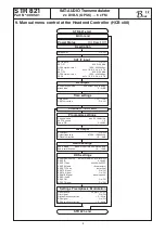
6.1 Adjustment with the Headend Controller
· Adjustment of the addresses at the Bus Extender BEB x00 and at the modules
· Activation of the programming mode on each module by selecting the line (BEB x00) and the module position (01... 15) at
the Headend Controller(HCB x00)
→
yellow LED illuminates until the beginning of the parameter adjustment
· Adjustment of the STR 821 parameters (see chapter 9)
→
green LED is switched on
· After the programming the STR 821 will be automatically switched into the operating mode
→
yellow LED flashes shortly/ green LED is switched on
6.2 Adjustment with the PC/ laptop
· Prerequisite for the remote programming is an “online-connection” according the IP standard and an ethernet connection at the
PC/ laptop
· Adjustment of the line/ position addresses at the Bus Extender BEB x00 as well as at the modules
· At the Headend Controller HCB x00 input IP address (e.g. 192.168.001.001)
· For “direct connection” between a PC and HCB x00 use crossover cable (RJ 45)
· For connection over a HUB use a normal straight throught patch cable
· Start-up HTML browser and put in IP address as target address
· If connected correctly the web interface will be opened on the pc and a blue LED (LINK) at the HCB x00 will be lit up.
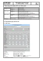
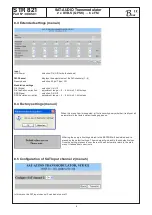
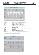
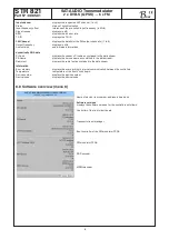
· All adjustments of the modules are specified on the web interface.
SAT IF input coupler ”input”
SAT IF input coupler ”output”
Operating voltage/
control bus
LED ”STANDBY” (red)
LED ”READY1” (green)
LED ”READY2” (green)
LED ”ADDR.” (yellow)
Address selector
Output coupler ”input”
Output coupler ”output”
B
LINE
SAT-AUDIO TRANSMODULATOR
2 x DVB-S (QPSK)
6 x FM
Type:
Part No :
STR 821
9085.01
SAT-IF IN
950 ... 2150 MHz
INPUT LEVEL
52 ... 92 dBµV
FM
SUPPLY CURRENT
0.85 A
OUT
87.5 ... 108 MHz
OUTPUT LEVEL
max. 6 x 110 dBµV
X1
SAT-AUDIO TRANSMODULATOR
2 x DVB-S (QPSK)
6 x FM
Type:
STR 821
Part No.:
9085.01
SAT-IF IN
950...2150
MHz
INPUT LEVEL
52...92
dBµV
FM OUT
87.5...108
MHz
OUTPUT LEVEL
max. 6 x 110 dBµV
SUPPLY CURRENT 0.85
A


