Dust Collector Function
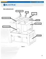
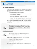
This unit is equipped with an auto pulse dust collector that provides suction to separate
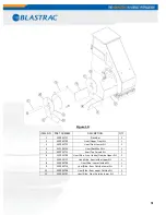
the dust from the shot. Refer to Figure 5 for the location or items discussed in this
section.
The central part of the dust collector is the filter chamber. Dust laden air enters the
chamber from the blast head through the exhaust hose and into the dust collector
inlet connection located on the center, front side of the dust collector. The dirty air
passes through a plenum and flows through an array of nine vertically mounted,
specially designed filter cartridges. Dust is captured on the surface of these filters
allowing clean air to pass to the clean air portion of the dust collector where it exhausts
to the open atmosphere through the silencer box.
The dust that was trapped on the external surface of the filters is periodically
removed by pulsing the filters with a burst of compressed air released from the
header tank by a diaphragm valve. The air is delivered via one of three blow-down
tubes. This momentary pulse of air allows the dust to fall into the dust bags at the
bottom of the filter chamber. Three filters are pulsed at a time, in sequence,
determined by a timer board located in the control box located on the front of the
dust collector, just above the inlet. This timer board is usually set to pulse a three
filter bank every ten seconds. The timer board determines the time between pulses
and the duration of each pulse. Venturi valves are located above each filter for
maximum filter cleaning efficiency.
20
Summary of Contents for 1-16DB4-V2
Page 1: ...SERVICE MANUAL 1 16 DB4 V2 VERSION 1 1 www blastrac com 1 800 256 3440...
Page 36: ...Check for leaks after starting theengine...
Page 38: ...35...
Page 40: ...36...
Page 42: ...37...
Page 44: ...38...
Page 46: ...39...
Page 50: ...BLASTRAC RS IN SURFACE PREPARATION Figure 12 43...
Page 57: ...BLASTRAC VATORS IN SURFACE PREPARATION Blast Head Assembly Figure 14 48...

