background image


BG-250-230/60 

Electric 230v, 1ph  

Concrete Grinder 


Blastrac 

6215 N. Aluma Valley Dr. 

Oklahoma City, OK  73121 

1-800-256-3440 

© Copyright Blastrac 


Revision (A) 10-20-05 

Summary of Contents for BG-250-230

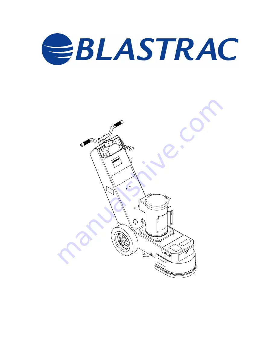
Page 1: ...BG 250 230 60 Electric 230v 1ph Concrete Grinder Blastrac 6215 N Aluma Valley Dr Oklahoma City OK 73121 1 800 256 3440 Copyright Blastrac Revision A 10 20 05...

Page 2: ...60 Technical Data October 2005 Contents Chapter 1 1 1 Rating 1 2 Unit specifications 1 3 Operating range and correct usage 1 4 Machine type designation 1 5 Advice for operators of the machine Copyrig...

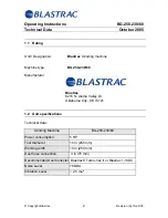
Page 3: ...N Aluma Valley Dr Oklahoma City OK 73121 1 2 Unit specifications Technical data Grinding Machine BG 250 230 60 Power consumption 5 HP Tool diameter 10 in 250 mm Working width 10 in 250 mm Dust hose c...

Page 4: ...ange and correct usage The BG 250 230 60 is exclusively designed to grind horizontal surfaces The machine may not be used for other purposes The manufacturer will not be liable for damage or injury re...

Page 5: ...will vary depending on the location If the sound level reaches 85 db A or more the operator and the surrounding personnel must wear OSHA approved hearing protection Verify that you always rest the mac...

Page 6: ...nts Chapter 2 2 1 Warnings and symbols 2 2 Organizational measures 2 3 Personnel selection and qualification 2 4 Safety precautions applicable to some operating sequences 2 5 Special work instructions...

Page 7: ...perational safety In these Operating Instructions this symbol will be shown next to safety precautions that are to be taken in order to increase safe operation of the machine Follow these instructions...

Page 8: ...Instructions BG 250 230 60 Safety October 2005 Copyright Blastrac 7 Revision A 10 20 05 Information instructions and restrictions with regard to possible risks to personnel and or to extensive machin...

Page 9: ...20 05 Warning against dangerous voltages Indications relating to protective devices in electrical appliances Indications where consultation with the manufacturer is required Instructions relating to...

Page 10: ...h traffic regul The Operating Instructions must be supplemented by instructions including the duty to supervise and report relating to particular working practices for e Personnel entrusted with worki...

Page 11: ...ts specified by the manufacturer This is always guaranteed if original spare parts are used Intervals for recurring checks and inspections specified in these Operating Instructions must be complied wi...

Page 12: ...icable to some operating sequences Ban any method of working that impairs safety Some measures have to be taken in order to operate the machine in safe and operative conditions Only operate the machin...

Page 13: ...pter 2 6 for any servicing work on the machine vicing the Follow any special safety instructions in the various chapters on ser machine See chapter 7 1 7 9 Adjustment servicing and inspection work and...

Page 14: ...es need to be taken off or dismantled during service and repair these safety devices must be reinstalled and inspected immediately after completion of the servicing and repair work Make sure that proc...

Page 15: ...of the Maintenance Mode Definition The machine is in a safe condition when it cannot generate any hazard Putting the equipment in the Maintenance Mode means Lift up the machine see Chapter 5 Switch o...

Page 16: ...sons under the guidance and supervision of a skilled electrician as well as in accordance with the electrical engineering regulations Any machine if it is not used according the regulations may be haz...

Page 17: ...0 230 60 General October 2005 Copyright Blastrac 16 Revision A 10 20 05 Contents Chapter 3 3 1 Range of application 3 2 Scope of supply 3 3 Description of the machine 3 4 Operating elements 3 5 The to...

Page 18: ...To remove residual mineral adhesives o Smoothing of concrete 3 2 Scope of supply Scope of supply of the machine Grinding Machine BG 250 230 60 Dust collector Turbo Vac II or 1 13DC Optional Dust hose...

Page 19: ...Driving motor 10 Brush seal see Fig 3 4 The Blastrac grinding machine BG 250 230 60 can produce a pattern of 10 inches 250 mm and distinguishes itself by its high economic efficiency and easy handlin...

Page 20: ...3 2 Before Switching on the BG 250 230 60 the front part of the grinding machine must be lifted by pushing down on the handgrip 2 and pulling back on the jack stand operating lever 1 When the machine...

Page 21: ...Jack Stand Operating Lever and make sure the diamond disc is off the ground and the machine is secure before starting Verify all electrical connections are made and surrounding area is clear Grab hand...

Page 22: ...tructions BG 250 230 60 General October 2005 Copyright Blastrac 21 Revision A 10 20 05 3 5 The Tools Fig 3 4 1 Brush seal 5 Flexible Coupling 2 Diamond grinding disc 6 Bearing Unit 3 Adapter 7 Jack st...

Page 23: ...ntact Blastrac with any questions regarding the operation or maintenance of the machine Never operate the machine if you are unsure Be sure the BG 250 230 60 is clean and free of any debris before ope...

Page 24: ...230 60 Transport October 2005 Contents Chapter 4 4 1 Unit specifications 4 2 Manual mode of moving the machine 4 3 Transport with cranes or lifts 4 4 Transport of the machine with vehicle Copyright Bl...

Page 25: ...0 00 x 18 00 x 51 00 508 x 457 x 1295 31 x 19 x 29 788 x 483 x 737 Weight empty 68lbs 31 kg 120 lbs 55 kg 4 2 Manual mode of moving the machine In order to move the machine press down the handgrips to...

Page 26: ...weight from chapter 4 1 Unit specifications Never fasten a sling or lifting device to or around the handle of the machine The handle will break causing damage and injury Place three slings at the poi...

Page 27: ...achine with straps and block wheels to make sure the machine will not move during transport Never transport the machine with gasoline in the tank Enclosed trailers or vehicles may be dangerous due to...

Page 28: ...Operating Instructions BG 250 230 60 Initial Operation October 2005 Contents Chapter 5 5 1 Preparation for initial operation 5 2 Initial operation Copyright Blastrac Revision A 10 20 05 27...

Page 29: ...hapter 7 Maintenance of this manual Check the dust hose for damages Connect the grinding machine and the dust collector with the dust hose Use hose clamps at the connections Make sure the dust bin of...

Page 30: ...lling back on the operating lever 1 Pulling back on the operating lever 1 will lower the kick stand and take the weight off the grinding disc Be sure machine is stable prior to starting the motor When...

Page 31: ...itch 13 On Button Starting See Handgrip and Operating Lever and make sure the diamond disc is off the ground and the machine is secure before starting Verify all electrical connections are made and su...

Page 32: ...of the machine This red button is also used as OFF switch Stopping 2 1 3 4 5 13 The grinding machine must be lifted by pushing down on the handgrip 2 and pulling back on the operating lever 1 Pulling...

Page 33: ...Operating Instructions BG 250 230 60 Initial Operation October 2005 Notes Copyright Blastrac Revision A 10 20 05 32...

Page 34: ...peration October 2005 Contents Chapter 6 6 1 Operation 6 2 Switching off the machine 6 3 Emergency Shutdown 6 4 Safety shutdown 6 5 Restarting after a fault 6 6 Procedures after lengthy down time Copy...

Page 35: ...e sure all fasteners are tight and secure Pay special attention to those that connect drive components Before switching on make sure that all guards are in place Be sure the dust collector is correctl...

Page 36: ...ne read sections chapter 5 1 and 5 2 of these operating instructions Never start the machine if you are not completely confident on how to operate the machine You should grind in fan shaped movements...

Page 37: ...dnesses Segment hardness may be matched to specific jobs resulting in successful applications and improved diamond life 6 2 Switching off the machine 2 1 3 4 5 13 The grinding machine must be lifted b...

Page 38: ...chine parts are stopped Observe the Maintenance Mode condition chapter 2 6 Read and understand the entire Blastrac Operating Instructions before operating or servicing this machine Do not depend on in...

Page 39: ...nd so that the brush seals and the flexible coupling are not touching the floor Clean the machine and cover it with a tarp 2 After storage Be sure all fasteners are tight and secure Check to make sure...

Page 40: ...s 7 2 Maintenance and inspection list 7 3 Repairing 7 4 Grinding disc replacement assembly 7 5 Bearing Unit 7 6 Flexible coupling 7 7 The V Belt drive 7 8 The driving motor 7 9 Additional maintenance...

Page 41: ...ations on preventative actions The time indications are based on uninterrupted operation When the indicated number of working hours is not achieved during the corresponding period the period can be ex...

Page 42: ...amage Check the hose inside of the BG 250 230 60 for damage Clear any foreign matter from the coupling of the grinding disc Make sure that the dust bin of the dust collector is emptied Check the grind...

Page 43: ...el You should stock all spare or wear parts that cannot be supplied quickly As a rule downtime is more expensive than the cost for the corresponding spare part Screws that have been removed must be re...

Page 44: ...e against tilt back with a block 2 about 17 75 45 cm long Shake machine to make sure it will not move 3 Unscrew the four countersunk head screws 7 in the grinding disc 4 Remove the grinding disc Fig 7...

Page 45: ...r lubricating put the machine on the kick stand 4 let the machine run approximately 5 min to squeeze out the excess of grease from the housing 1 at the points shown 3 Finally wipe the excess of grease...

Page 46: ...isc check the condition of the coupling If the coupling is cracked or is sitting on an angle with no load on the disc it should be replaced Immediately shut down the machine if unusual vibrations or n...

Page 47: ...and will result in very high V belt temperatures This will cause premature V Belt wear Temperatures over 160 F 70 C for a long period will decrease the working life and the efficiency of the V belt T...

Page 48: ...the motor base 4 Remove the V Belt Fig 7 5 Assembly 1 Put on a new V Belt 2 Move the motor up to the operator panel using tensioning screw attached to the motor base 3 Hand tighten the motor fastenin...

Page 49: ...nsion results in damaged bearings at the motor or bearing unit To properly tension the belts press the belt with your thumb midway between the pulleys as indicated in figure 7 6 When properly tensione...

Page 50: ...having the following spare parts on stock to avoid long down times Part No Description Qty 000118 Flexible coupling 2 P004077 Count S Head Screw 20 B20507 Spacer tube 6 CG 1020DB Diamond disc 1 B21014...

Page 51: ...Operating Instructions BG 250 230 60 Maintenance October 2005 Notes Copyright Blastrac Revision A 10 27 05 50...

Page 52: ...Operating Instructions BG 250 230 60 Electrical October 2005 Contents Chapter 8 8 1 Directions for electrical engineering 8 2 Electric circuits diagrams Copyright Blastrac Revision A 10 27 05 51...

Page 53: ...may only be undertaken by a skilled electrician or by trained persons under the guidance and supervision of a skilled electrician as well as in accordance with the electrical engineering regulations...

Page 54: ...Operating Instructions BG 250 230 60 Electrical October 2005 8 2 Wiring Schematic Copyright Blastrac Revision A 10 27 05 53...

Page 55: ...Operating Instructions BG 250 230 60 Troubleshooting October 2005 Contents Chapter 9 9 1 Grinder troubleshooting 9 2 Electrical troubleshooting Copyright Blastrac Revision A 10 27 05 54...

Page 56: ...heck flexible coupling Tighten screws in the grinding disc Unusual noises Defective axle bearing Wrong tension of the V belt Dirt and debris in flexible coupling Check axle bearing and replace if nece...

Page 57: ...rdance with the electrical engineering regulations Prior to any repair work on the machine or its drives the machine must be secured against unintentional starting Put the machine in Maintenance Mode...

Page 58: ...ating Instructions BG 250 230 60 Spare Parts October 2005 Contents Chapter 10 10 1 Spares Parts List BG 250 230 60 4 9 11 27 25 69 3 42 26 28 21 1 2 1 8 37 64 67 Copyright Blastrac Revision A 10 27 05...

Page 59: ...Operating Instructions BG 250 230 60 Spare Parts October 2005 42 67 69 68 44 6 15 7 18 16 64 23 24 Copyright Blastrac Revision A 10 27 05 58...

Page 60: ...Operating Instructions BG 250 230 60 Spare Parts October 2005 37 34 5 33 8 35 36 12 19 13 32 19 32 33 38 Copyright Blastrac Revision A 10 27 05 59...

Page 61: ...Operating Instructions BG 250 230 60 Spare Parts October 2005 45 43 48 47 50 16 41 46 59 57 61 60 9 62 58 57 Copyright Blastrac Revision A 10 27 05 60...

Page 62: ...Operating Instructions BG 250 230 60 Spare Parts October 2005 10 11 56 31 55 30 29 53 54 39 40 2 3 17 27 26 16 19 18 14 36 20 54 66 65 63 19 51 52 30 14 Copyright Blastrac Revision A 10 27 05 61...

Page 63: ...103 WASHER FLAT 5 16 DIA 17 4 500190 SCR CAP HEX 0 312 18 X 1 000 18 5 500114 WASHER LOCK 5 16 19 11 5001040 WASHER FLAT 3 8 20 2 5007670 SCR CAP HEX 0 375 16 X 1 000 21 1 P000008 DECAL BLASTRAC 4 3 8...

Page 64: ...VOT PIN LOWER 52 1 DG58 GUIDE BOLT ADJUSTING ROD PIN 53 1 DG59 ADJUSTING ROD PIN 54 2 DG60 CLEVIS ROD END 55 1 DG52 LEVER 56 1 DG50 KNEE LEVER 57 6 B20507 B20507 TUBE SPACER 58 1 118 FLEXIBLE COUPLING...

Page 65: ...Operating Instructions BG 250 230 60 Spare Parts October 2005 Notes Copyright Blastrac Revision A 10 27 05 64...

Reviews: