ADJUSTING THE BRAKES
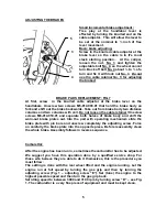
Small incremental brake adjustment :
Free play at the handlebar lever is
effected by turning the knurled end on the
cable adjustor. This will allow the lever to
be set at the nominal to ¼ inch of free
lever movement.
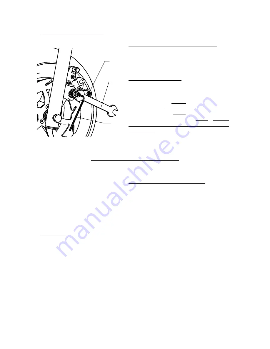
Basic brake adjusting:
Screw in the knurled cable adjustor at the
brake lever so the cable is in it’s most
slack starting position.. At the caliper,
loosen the nut, No. 3 and tighten the
adjustable bolt No. 4, so the wheel cannot
turn. Back off bolt No. 4 about ¼ to ½ of a
turn and fix it with lock nut No. 3
. Do not
use the cable retainer No. 5 for adjusting
the brakes!
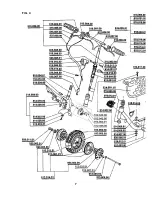
BRAKE PADS REPLACEMENT: FIG.7
At first, screw in the knurled cable adjustor at the brake lever on the
handlebars. Unscrew two screws M5-914.003.01 that hold the brake body on
fork and shift out the brake backwards. Take out from brake body two distance
columns and two columns with coil. Do not loosen the cable retainer! Unscrew
screws M6-914.010.01 and separate both halves of brake body and shift the
worn-out brake plates out. Into the part with operating mechanism slide the
brake plate with pin bore and unscrew completely the adjusting screw. Force
on carefully the brake plate into the opposite piece. Before reassembly clean
the whole brake. Assembly follows in reverse sequence.
Carburettor:
After the engine has been run in, sometimes the carburettor has to be adjusted.
We suggest you have this operation done by a qualified service shop. For
those who believe they are able to do it themselves, this is the procedure you
must follow:
The setting is done with the rear wheel lifted and the engine running. Let the
engine run at full speed by turning the gas grip and then by turning the
adjusting screw (Fig. 1 – adjusting screw “E”). Set (tune) the engine to the
highest possible speed and then turn the gas grip back.
Set idling speed to between 3000 and 3100 rpm by turning screw “D” – see Fig.
1. The carburettor is a very fine piece of equipment and must be kept clean.
5
3
4
5
Summary of Contents for Blatino
Page 1: ...USER S MANUAL SCOOTER WITH AUXILIARY ENGINE...
Page 2: ......
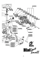
Page 10: ...7 FIG 4...
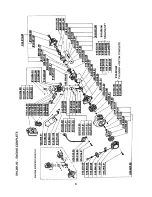
Page 11: ...8...
Page 12: ...9...
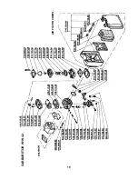
Page 13: ...10 AIR FILTER COMPL CARBURETOR WYK 42...
Page 14: ...11 916 072 02 512 055 00 FRONT BRAKE COMPLETE 512 056 00 REAR BRAKE COMPLETE 916 072 02...
Page 18: ......
Page 19: ......
Page 20: ...COPYRIGHT BLATA 2007 C...

