background image

10

www.blaubergventilatoren.de

VENTO V50-1 / V50-1  S / V50-1 Pro / V50-1 S Pro
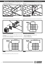
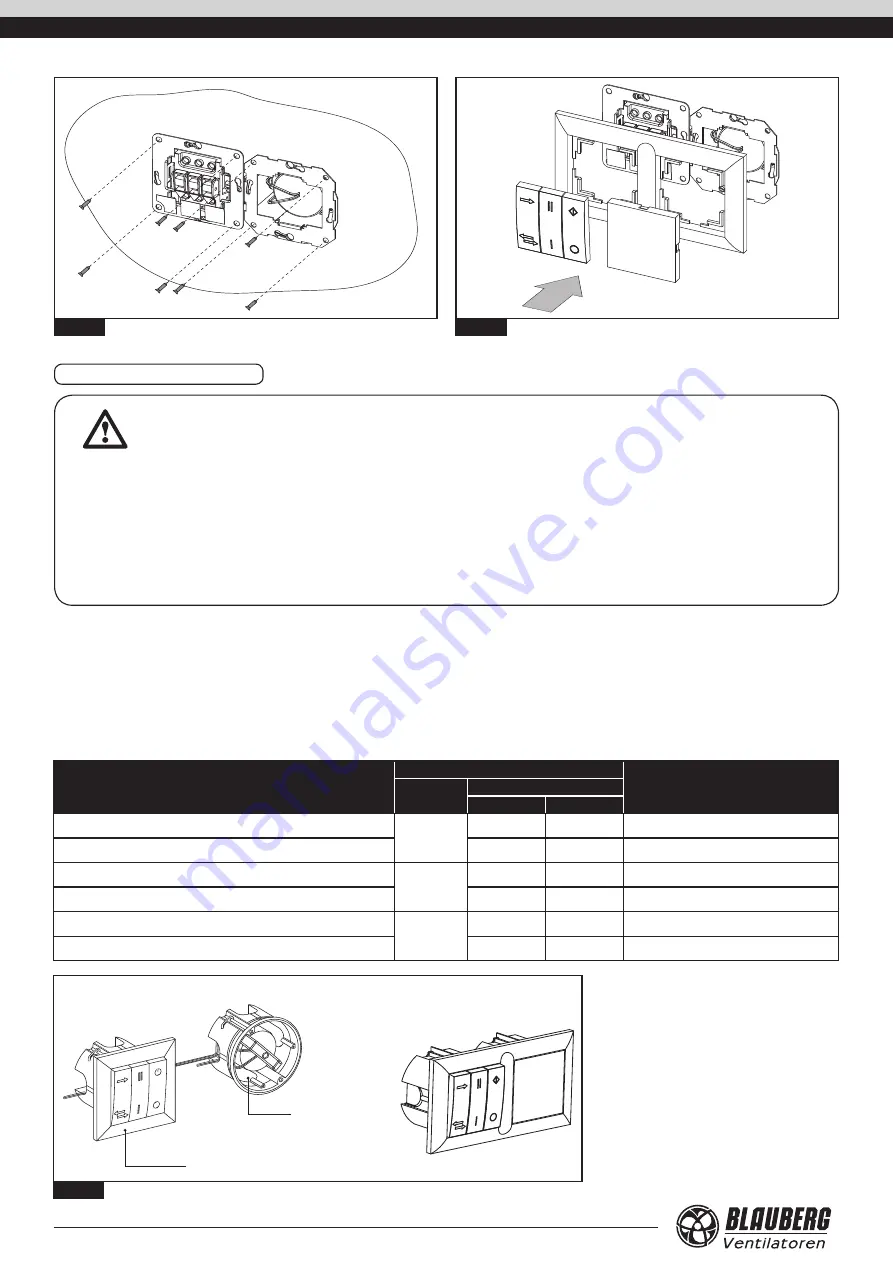
Fig. 20.

Fig. 21.

17. 

Install the power and control unit in the wall recess, Fig. 20.

18. 

Install the frame, the buttons and the plug in the reverse order, Fig. 21.

CONNECTION AND CONTROL

WARNING

Read the operation manual prior to any electric installations. Connection of the unit to power mains is allowed by a 

qualified electrician only. 

The rated electrical parameter are stated on the rating plate. No modifications of internal connections are allowed and will 

result in void warranty. 

Connect the unit only to power mains with valid electric norms and standards. The unit must be connected to a correct 

mounted socket with a grounded terminal or connected to a fixed installed cable.

Follow the respective electric standards, safety rules (DIN VDE 0100), TAB der EVUs. The house cabling system must be 

equipped with an automatic switch at the external input. Connect the unit to power mains through the automatic switch. The 
contact gap on all poles at least 3 mm (VDE 0700 T1 7.12.2 / EN 60335-1).

Install the automatic switch to ensure prompt access.

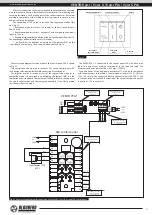
The unit is controlled with the external control panel SEA or the control 

and power unit SEA-T12. The control devices are available on separate order if 

not included into the delivery set of the unit model. 

The control and power unit SEA-T12 consists of a control panel and a 12 

W power transformer, Fig. 22. In case of the control panel SEA either power 

transformer AT-12 or AT-40 are used and are available upon separate order. 

The unit is rated for connection to single-phase alternating current power 

mains 230 V / 50 Hz or 120 V / 60 Hz, depending on the used transformer type. 

Separate power supply must be provided both to the control panel and to 

the ventilation unit to control the  automatic shutters. The control and power 

unit modifications are customer selected depending on power mains voltage 

and transformer power in compliance with the table 2.

Table 2. Control panel technical data

Control and power unit name

Transformer parameters

Note

Power [W]

Voltage [V]

Input

Output

Control and power unit SEA-T12 

12

230 / 50 Hz

12 / 50 Hz

Rated for connection up to 4 units 

Control and power unit SEA-T12 (120 V / 60 Hz)

120 / 60 Hz

12 / 60 Hz

Rated for connection up to 2 units 

Control panel SEA + transformer AT-40 

40

230 / 50 Hz

12 / 50 Hz

Rated for connection up to 12 units 

Control panel SEA + transformer AT-40 (120 V / 60 Hz)

120 / 60 Hz

12 / 60 Hz

Rated for connection up to 6 units 

Control panel SEA + transformer AT-12

12

230 / 50 Hz

12 / 50 Hz

Rated for connection up to 4 units 

Control panel SEA + transformer AT-12 (120 V / 60 Hz)

120 / 60 Hz

12 / 60 Hz

Rated for connection up to 2 units 

Control panel SEA and power transformer AT

Control and power unit SEA-T12

Control panel SEA 


Transformer 

Fig. 22.

Summary of Contents for 4058448022678

Page 1: ...VENTO V50 1 SINGLE ROOM REVERSIBLE UNIT WITH HEAT AND HUMIDITY RECOVERY OPERATION MANUAL EN...

Page 2: ...Safety rules 3 Transportation and storage rules 3 Manufacturer s warranty 3 Design and operating logic 4 Modifications and options 5 Delivery set 5 Technical data 6 Mounting 7 Connection and control...

Page 3: ...icky substances or fibrous materials The appliance is not designed for use in an inflammable and explosive medium Do not close or block the intake or exhaust vent of the appliance not to disturb the n...

Page 4: ...SEA T12 or the control panel SEA is used for operation mode control The delivery set of the units VENTO V50 1 Pro V50 1 S Pro includes the control and power unit SEA T12 consisting of the control pane...

Page 5: ...Pro The unit for the wall thickness from 120 up to 430 mm Equipped with the control panel and the control unit SEA T12 DELIVERY SET Unit 1 item Fixing set 1 item SEA T12 control and power unit for Pro...

Page 6: ...0 021 0 026 Max air flow m3 h 26 53 Sound pressure level at 1 m distance dB A 24 34 Sound pressure level at 3 m distance dB A 14 24 Outdoor sound pressure attenuation dB A 19 Transported air temperat...

Page 7: ...opic air ducts outer ventilation hood and laying out of electric cables final mounting before commissioning of a house It includes installation of the regenerator the filter connection of the ventilat...

Page 8: ...the back part of the ventilation unit Fig 14 7 Remove a screw from the bottom part of the ventilation unit and take off the front grille 8 Insert the dowels 5x25 in the wall and fix the ventilation u...

Page 9: ...l using the screws 4x40 from the delivery set 13 Install the front part of the outer ventilation hood 14 Install the control panel SEA T12 with a power unit inside a prepared hole in the wall see Fig...

Page 10: ...ery set of the unit model The control and power unit SEA T12 consists of a control panel and a 12 W power transformer Fig 22 In case of the control panel SEA either power transformer AT 12 or AT 40 ar...

Page 11: ...tion mode is determined by positioning the jumper JMP1 on the ventilation unit circuit board The jumper positioned in Flow In position sets the unit to supply mode and the jumper positioned in Flow Ou...

Page 12: ...5 The socket connectors of the connecting cable supplied with the unit are marked 1 to 5 and must be connected to the controller socket connectors marked 11 15 for outputs or 21 25 for inputs Cable ch...

Page 13: ...2W transformer wire leads to the contacts A1 35 36 of the controller A1 SEA using the socket connector at the cable K2 The cable is included into delivery set of the 40W transformer model Then connect...

Page 14: ...ow green white grey brown yellow green white 1 grey 2 brown 3 yellow 4 green 5 white 1 grey 2 brown 3 yellow 4 green 5 white 1 grey 2 brown 3 yellow 4 green 5 white 1 grey 2 brown 3 yellow 4 green 5 w...

Page 15: ...year Remove the screw in the bottom part of the fan grille remove and clean the grille Disconnect the wires from the ventilation unit by using the connectors Remove the four screws and take off the v...

Page 16: ...the approximation of the laws of the Member States relating to electromagnetic compatibility This certificate is issued following test carried out on samples of the product referred to above Approval...

Page 17: ..._____________________________________________ _______________________________________________________________________________________ __________________________________________________________________...

Page 18: ..._____________________________________________ _______________________________________________________________________________________ __________________________________________________________________...

Page 19: ..._____________________________________________ _______________________________________________________________________________________ __________________________________________________________________...

Page 20: ...www blaubergventilatoren de VENTO V50 1 v 1 6 EN...

Reviews: