


www.blaubergventilatoren.de
7
VENTO V50-1 / V50-1 S / V50-1 Pro / V50-1 S Pro
MOUNTING
WARNING
The air duct of the ventilation unit must not be closed with curtains, drapes and other clothes to
avoid dust accumulation on the materials.
The curtains may impair air circulation in the room and efficiency of the ventilation unit.
The unit is designed for external through-the-wall installation inside a
prepared square hole in the outer wall of the building.
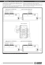
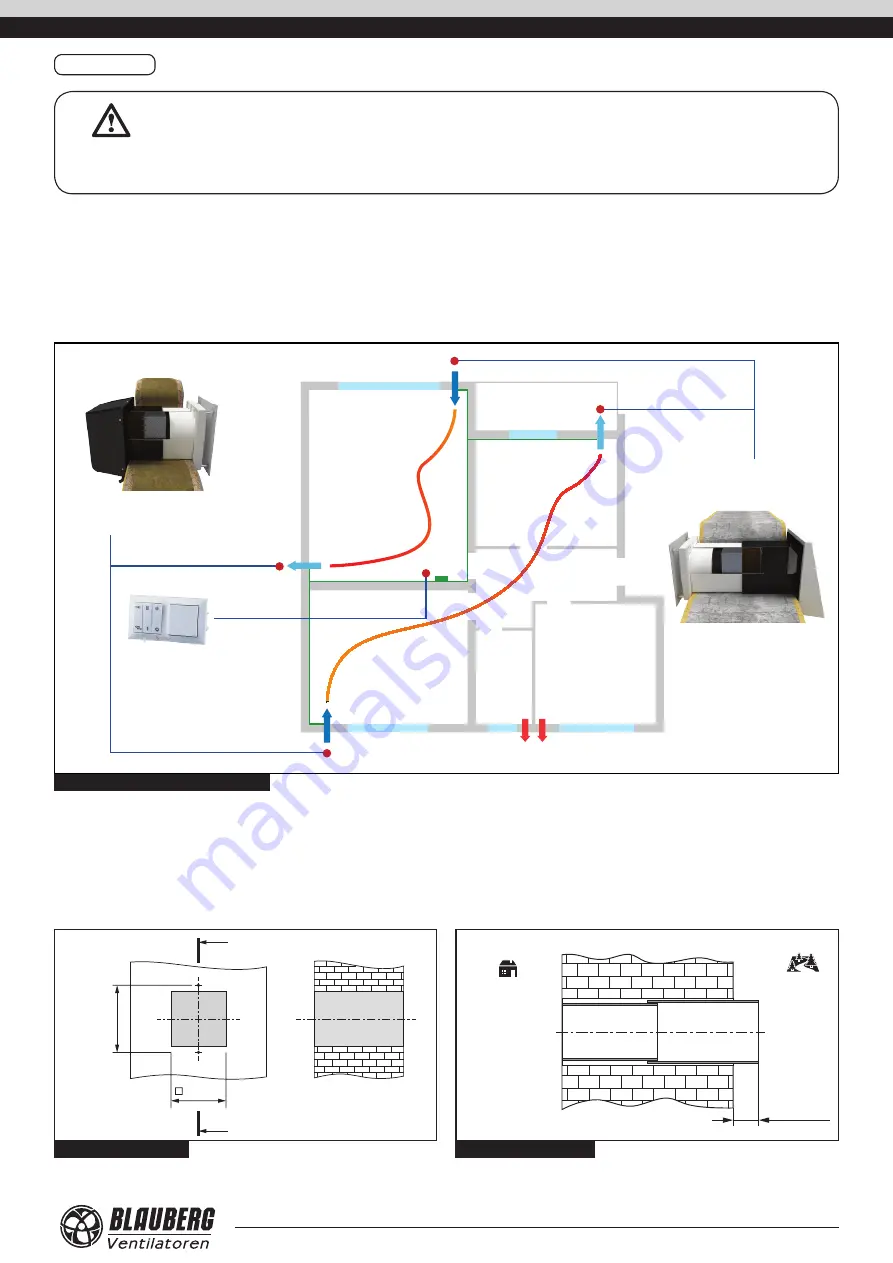
The best ventilation solution is pairwise installation of reverse phase
connected units. Some units ensure supply of fresh air to the room and
the other units provide air extract from the premise. This allows to arrange
the most efficient balanced ventilation.
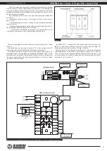
In case of brand new construction the units are mounted in two stages:
•
pre-installation at the stage of the indoor finishing and outer decorative
wall finishing. It includes installation of the telescopic air ducts, outer
ventilation hood and laying out of electric cables.
•
final mounting before commissioning of a house. It includes installation
of the regenerator, the filter, connection of the ventilation unit and
automation.
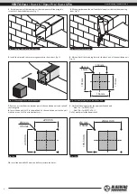
Kitchen
Bathroom
Room
Room
Room
Сorridor
Balcony
VENTO V50-1 S Pro unit installation
example into a thin wall
SEA-T12 control and
power unit
VENTO V50-1 Pro unit installation
example into a wall with standard
thickness
Fig. 8. Mounting example for VENTO V50-1
Mounting sequence:
1.
Prepare a square core hole through the outer wall. The size is shown in Fig. 9.
Prepare two holes for the dowels 5x25 and insert dowels in the wall.
While mounting several connected in series units provide a recess for the cable
layout during the hole preparation to enable series connection of several units.
2.
Install the telescopic air duct in the wall. The protruding telescopic air duct
segment on outer wall side must be equal to the distance A, Fig. 10:
•
A = 10 mm (for VENTO V50-1);
•
A = 10-110 mm (for VENTO V50-1S).
180 mm
192 mm
A
A-A
A
max A
Inside
Outside
Fig. 9. Size of the core hole
Fig. 10. Size of the core hole


