background image

www.blaubergventilatoren.de

vento expert (Duo) a50/85/100 (Pro3) W v.2

10

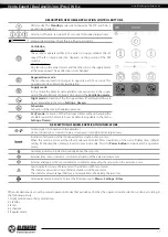
3. Fasten the supplied mounting template to the indoor wall using the adhesive tape. The large opening in the template must be coaxial 
with the air duct. For aligning the template with respect to the horizon line it is recommended to use a builder’s level.
Then mark the fastening holes for installation of the supplied dowels and drill the holes to a required depth. Route the power cable of the 
ventilator from the wall through the marked opening on the template.

207

   Ø 5

   Ø 180

87,5

138

103,5

137

85

   Ø 23

Hole marking for fasteners

4 holes

4. Press the side tabs to detach the front part of the indoor unit from its rear part.

ATTENTION! 

For the 

Vento Expert A50/85/100-1 W V.2


prior to mounting the front panel 

make sure that the thermal actuator 

rod is in the lowest position. 

Blinking of the white led indicator 

means that the thermal actuator is not 

in the low position!

5. Fix the rear part of the indoor unit on the wall using the screws supplied with the mounting kit of the ventilator. Remove the two screws 
that retain the transparent cover to enable access to the connection terminals.

6. Route the power cable as figured below and connect the 
ventilator to power mains in compliance with the external wiring 
diagram (refer to page 12).
Fix the power cable and the signal cables with a cable clamp. 
After completion of the electrical connection re-install the 
transparent terminal cover in site.

Cable clamp

Summary of Contents for 4058448053467

Page 1: ...egeneration ventilator USER S MANUAL EN Vento Expert A50 1 W V 2 Vento Expert A50 1 Pro3W V 2 Vento Expert A85 1 W V 2 Vento Expert A85 1 Pro3W V 2 Vento Expert A100 1 W V 2 Vento Expert A100 1 Pro3W V 2 Vento Expert Duo A30 1 W V 2 ...

Page 2: ...the Vento Expert Duo A50 85 100 Pro3 W V 2 unit and all its modifications Technical and maintenance staff must have theoretical and practical training in the field of ventilation systems and should be able to work in accordance with workplace safety rules as well as construction norms and standards applicable in the territory of the country The information in this user s manual is correct at the t...

Page 3: ...or the entire service life of the unit While transferring the unit control the user s manual must be turned over to the receiving operator UNIT INSTALLATION AND OPERATION SAFETY PRECAUTIONS Disconnect the unit from power mains prior to any installation operations Unpack the unit with care The unit must be grounded While installing the unit follow the safety regulations specific to the use of elect...

Page 4: ...ubstances in close proximity to the unit When the unit generates unusual sounds odour or emits smoke disconnect it from power supply and contact the Seller Do not open the unit during operation Do not direct the air flow produced by the unit towards open flame or ignition sources Do not block the air duct when the unit is switched on In case of continuous operation of the unit periodically check t...

Page 5: ...materials coarse dust soot and oil particles or environments favourable for the formation of hazardous substances toxic substances dust pathogenic germs NAME NUMBER Vento Expert Vento Expert Duo Indoor unit of the ventilator 1 pc 1 pc Air duct 1 pc 1 pc Air flow separator 3 6 pcs Sound absorbing material 1 pc Assembled cartridge 1 pc 1 pc Outer ventilation hood 1 pc 1 pc Remote control 1 pc 1 pc C...

Page 6: ...us parts access and water ingress protection rating is IP24 The unit design is constantly being improved so some models may be slightly different from those ones described in this manual Technical data are stated on the rating plate on the casing individually for each ventilation unit A protruding part of the air duct on the outer wall Depends on the used ventilation hood type L cartridge length D...

Page 7: ...n hood model Sound absorbing material A layer of sound absorbing material for attenuation of noise generated during the ventilator operation Vento Expert Duo Vento Expert FUNCTIONING OF THE AIR SHUTTERS FOR Vento Expert A50 85 100 1WV 2 The shutters are closed The shutters are open The ventilator consists of an indoor unit with a decorative front panel a cartridge an air duct with a sound absorbin...

Page 8: ...ccumulated in the regenerator In 70 seconds after the regenerator cools down the ventilator goes again to the extract mode and the cycle starts from the beginning In this mode in case of installation of two ventilators they operate with opposite rotation directions While one ventilator supplies air the other one extracts air Airsupply theventilatoroperatesinthesupplymodeirrespective of position of...

Page 9: ... wall hole For ease of installation use the polystyrene wedges included in the delivery set The air duct end must protrude for the distance A that enables installation of the outer ventilation hood The distance A is stated in the installation instruction for the ventilation hood A min 3 mm Fill the gaps between the air duct and the hole with mounting foam Polystyrene wedge Install the air duct wit...

Page 10: ...tach the front part of the indoor unit from its rear part ATTENTION For the Vento Expert A50 85 100 1WV 2 prior to mounting the front panel make sure that the thermal actuator rod is in the lowest position Blinking of the white led indicator means that the thermal actuator is not in the low position 5 Fix the rear part of the indoor unit on the wall using the screws supplied with the mounting kit ...

Page 11: ... the protecting paper layer outside Insert the roll in the air duct against stop to the cartridge Make a mark at the end of the air duct remove the sound absorbing mat and cut the roll according to the marking After that insert the ready roll into the air duct 9 Install the sectional air flow separators from outside Install a required number of the air flow separators in the air duct against stop ...

Page 12: ...bove wire cross section value is tentative The signal cable must be shielded The actual conductor cross section selection must be based on the wire type maximum wire temperature insulation length and installation method Use copper wires only for all the electric connections Connect the unit to power mains via the terminal block in compliance with the wiring diagram and terminal designation Connect...

Page 13: ...e controller the buttons located on the side of the indoor unit see the figure below the mobile application Blauberg Vento V 2 installed on a smartphone or a tablet POSITIONING OF THE DIP SWITCH Setup of ventilator operation mode 1 OFF Master unit 1 ON Slave unit Standby mode setup 2 OFF the ventilator is off in the Standby mode 2 ON the ventilator is running at the first speed in the Standby mode...

Page 14: ...Ventilation indicates forced activation of the supply ventilation mode of the ventilator This mode may be activated via the mobile application only Filter The filter clogging indicator starts blinking 90 days after installation of the cartridge In this case clean or replace the filters see the Technical maintenance section After replacement of the filters reset the filter timer using the mobile ap...

Page 15: ...Regeneration mode Ventilation mode Vento Expert The ventilator runs in the extract or in the supply mode at the set speed The fan rotation direction depends on the position of the DIP switch 3 Vento Expert Duo One fan runs in the extract mode and the other one in the supply mode at the same speed The air direction is not changed Timer control buttons Party mode the timer activates operation of the...

Page 16: ...ect the mobile device to the Wi Fi access point with the name FAN 16 ID Number characters stated on the ventilator casing under the front panel Wi Fi access point password 11111111 1 2 4 5 6 8 7 3 Enter the Blauberg Vento V 2 app and create a new connection as follows 1 Enter the app menu 2 Select Connection At home 3 If mobile device is connected to the Wi Fi access point without router select th...

Page 17: ...changing the ventilator operation mode 4 hours by default adjustable in the menu Settings Timers DESCRIPTION OF MOBILE APPLICATION INDICATORS Current type of connection to the ventilator Home connection or connection via a cloud server through Internet respectively Indicator of activation of the third speed after actuation of any sensor When this mode is active all the other modes are disabled Aft...

Page 18: ...rops down below the set point the turn off delay timer for the Boost mode is activated After the delay timer countdown the ventilator reverts to the previous speed setting Sensor 0 10 V actuation of the analogue 0 10V sensor If the 0 10 V control signal exceeds the set value the ventilator goes to the maximum speed After decrease below the set value the Boost delay timer is activated After its ope...

Page 19: ...gs for the date and time The ventilator filters must be serviced after every 90 hours of continuous operation The need to replace the filters is communicated by the indicator in the upper section of the Control menu Replace the filter and reset the filter timer To reset the filter timer via the mobile application go to Menu Settings Filter Then press the Reset filter timer button The 90 days are c...

Page 20: ...run with the same speed In case of actuation of any sensors for Vento Expert Duo only the affected ventilator goes to the maximum speed according to the humidity control scenario The rest of the ventilators continue to run with the same speed WI FI PARAMETER SETUP Setup of theWi Fi parameters is only possible on Master units To set up ventilatorWi Fi parameters via the mobile app go to Menu Connec...

Page 21: ...vices to the Master unit with its own wireless access point In case of connection of eight Slave units to the Master unit with its own wireless access point a mobile device may not be connected Wiring diagram 2 The Master units the Slave units and the mobile devices are connected to a Wi Fi access point of the router In this case the Master unit can operate with the number N of Slave units limited...

Page 22: ... restore access to the ventilator functions To enter the special setup mode press and hold the Ventilation button on the ventilator casing for 5 seconds until the beep and blinking of all the LED lights The ventilator continues in this mode for 3 minutes and then automatically revert to the previous settings To exit the Setup mode immediately once again press and hold the Ventilation button on the...

Page 23: ...ivated any loss of Internet connection provided by the home server may result in temporary loss of communication with the ventilator Create a new account for control of the Master ventilator For that open the mobile app and go to Menu Connection Through cloud server 1 Press the Add new account button 2 Enter a login a password and an e mail address for password recovery Then press the Apply button...

Page 24: ...me the indicator glowing goes down AIR FLOW BLOCKING FOR Vento Expert Duo Press the side tabs to detach the front part of the indoor unit from its back part and close the air duct Then open the latches and remove the front part of the front panel Remove the air flow separator by pulling one of the side clamps Install the front part of the front panel and press it gently to close the air duct The f...

Page 25: ...r the Vento Expert A50 85 100 1 W V 2 models prior to mounting the front panel make sure that the thermal rod is in the low position and the indica tor of the circuit board doesn t blink Vento Expert Duo 1 Press the side tabs on the indoor unit to take off the front part Then open the tabs and disconnect the front panel from the indoor unit Remove the filters for cleaning Assemble all the parts in...

Page 26: ...Even regular technical maintenance may not completely prevent dirt accumulation on the regenerator and the fans Clean the regenerator regularly to ensure its high regeneration efficiency Clean the regenerator with a vacuum cleaner not less than once a year 4 Battery replacement in the remote control as required In case of a long operation of the remote control the battery must be replaced No respo...

Page 27: ...mpeller Loose screw connection in the ventilator casing or in the outer ventilation hood Tighten the screws of the ventilator or the outer ventilation hood STORAGE AND TRANSPORTATION REGULATIONS Store the unit in the manufacturer s original packaging box in a dry closed ventilated premise with temperature range from 5 C to 40 C and relative humidity up to 70 Storage environment must not contain ag...

Page 28: ...in the user s manual Contact the Seller for warranty service The manufacturer s warranty does not apply to the following cases User s failure to submit the unit with the entire delivery package as stated in the user s manual including submission with missing component parts previously dismounted by the user Mismatch of the unit model and the brand name with the information stated on the unit packa...

Page 29: ...www blaubergventilatoren de Vento Expert Duo A50 85 100 Pro3 W V 2 29 ...

Page 30: ...www blaubergventilatoren de Vento Expert Duo A50 85 100 Pro3 W V 2 30 ...

Page 31: ...e INSTALLATION CERTIFICATE The Vento Expert _________________ unit is installed pursuant to the requirements stated in the present user s manual Installation Stamp Company name Address Phone Number Installation Technician s Full Name Installation Date Signature The unit has been installed in accordance with the provisions of all the applicable local and national construction electrical and technic...

Page 32: ...www blaubergventilatoren de B133 4EN 06 ...

Reviews: