www.blaubergventilatoren.de
7
Box-D
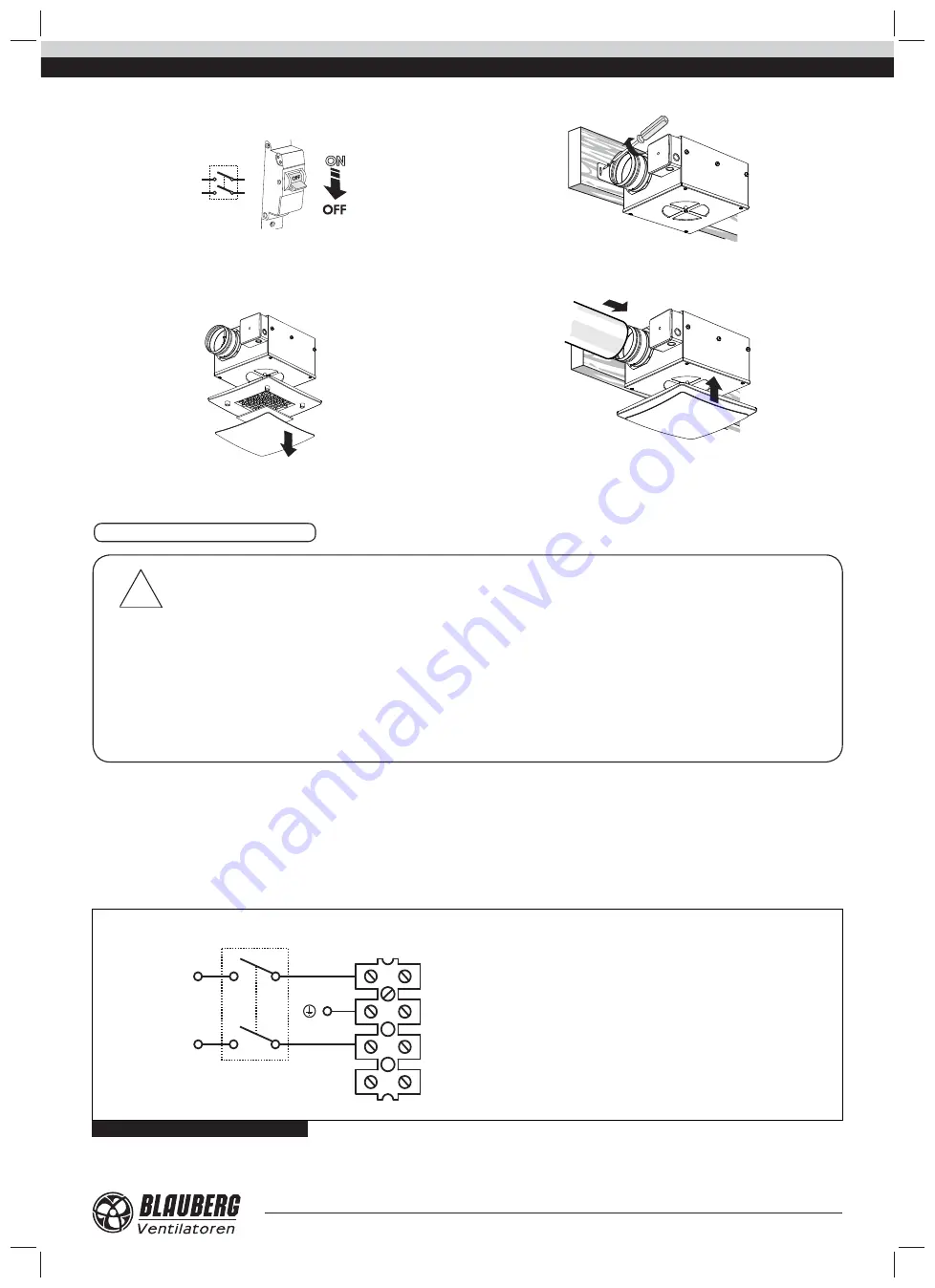
Mounting sequence for the
side mounting
:
1. Cut off power supply.
QF
2. Disassemble the fan:
- Take off the front panel and the fi lter.
- Remove the screw and take off the grille.
- Screw the bracket for the side mounting to the fan.
3. Screw the fan to the side surface.
4. Connect the air duct to the fan and fi x it with a clamp. Assemble the fan
in the reverse order.
The fan is rated for connection to single-phase alternating current power
mains 230 V / 50-60 Hz.
The recommended rated automatic switch trip current is 0.6 A.
The electric connections must be performed with insulated, durable
and heat-resistant wires with a matching cross section, in any case not
below 0.5 mm2. When selecting conductors take into account the maximum
permissible wire heating temperature, depending on the type of wire, its
insulation, length and laying method, either open installation, cable channel
installation or in-wall wiring.
The wiring diagram of the fan is shown in Fig. 4. The fan is powered
through the external terminal box.
Cut power supply to the fan off by turning the automatic electric switch
QF to OFF position. Take steps to prevent activation of the automatic switch
prior to fi nishing mounting.
CONNECTION TO POWER MAINS
!
WARNING
Read the operation manual prior to any electric installations. Connection of the fan to power mains is allowed by a qualifi ed
electrician only.
The rated electrical parameters of the fan are stated on the rating plate. No modifi cations of internal connections are
allowed and will result in void warranty.
Connect the fan only to power mains with valid electric standards.
Follow the respective electric standards, safety rules (DIN VDE 0100), TAB der EVUs. The house cabling system must be
equipped with an automatic switch at the external input. Connect the fan to power mains through the automatic switch. The
contact gap on all poles at least 3 mm (VDE 0700 T1 7.12.2 / EN 60335-1).
The automatic switch trip current must be in compliance with the fan current consumption, refer Table 1. Ensure prompt
access to the automatic switch installation place.
N
PE
L
1
2
3
4
L
X1
QF
~ 230 V / 50-60 Hz
Х1
- terminal block;
QF
- automatic electric switch (not included into delivery set);
L
- live;
PE
- protective earthing;
N
- zero.
N
Fig. 4. Wiring diagramm


