background image

www.blaubergventilatoren.de

iso Box-f(r)

10

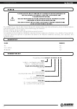
DISCONNECT THE POWER SUPPLY PRIOR TO ANY OPERATIONS WITH THE UNIT.

CONNECTION OF THE UNIT TO POWER MAINS IS ALLOWED BY A QUALIFIED 

ELECTRICIAN WITH A WORK PERMIT FOR THE ELECTRIC UNITS UP TO 1000 V AFTER 

CAREFUL READING OF THE PRESENT USER’S MANUAL. THE RATED ELECTRICAL 

PARAMETERS OF THE UNIT ARE GIVEN ON THE MANUFACTURER’S LABEL. 

ANY TAMPERING WITH THE INTERNAL CONNECTIONS IS PROHIBITED AND WILL VOID 

THE WARRANTY.

•  The unit is rated for connection to 1~230 V/50 Hz power mains. 
•  The unit must be connected to power mains using insulated electric conductors (cables, wires). The actual wire cross section selection 

must be based on the maximum load current, maximum conductor temperature depending on the wire type, insulation, length and 
installation method. 

•  The external power input must be equipped with an automatic circuit breaker built into the stationary wiring to open the electric 

circuit in case of overload or short-circuit. The circuit breaker installation place must provide quick access for emergency shutdown 
of the unit. The trip current of the automatic circuit breaker 

QF

 must exceed the maximum current consumption of the unit (refer 

to the technical data table).  The recommended trip current of the circuit breaker is the next current in the standard trip current row 
following the maximum current of the connected unit.  The automatic circuit breaker is not included in the delivery set.

ANY TAMPERING WITH THE INTERNAL CONNECTIONS IS PROHIBITED  

AND WILL VOID THE WARRANTY.

The recommended cross section of conductors (cables, wires) is 0.75 mm

2

The recommended circuit breaker nominal current should be not less than 1 A. 

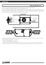
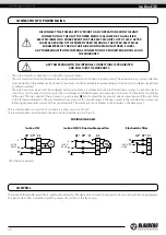
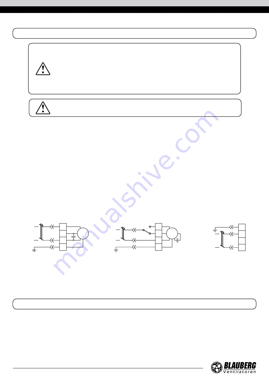
WIRING DIAGRAMS 

Iso Box-F(R)

Iso Box-F(R) V2 Duo double-speed fan

Electrostatic filter

X3

L

L

QF* XP*

PE

N

N

PE

C

M

~230 V

50 Hz

X3

L1
L2

L

QF* XP*

PE

N

PE

N

S1

C

M

Low

High

~230 V

50 Hz

X1

PE

N

PE

QF* XP*

L

LF

N

L

~230 V

50 Hz

*Purchased separately. 


CONTROL

The speed of the double-speed fan is switched (Low/High) at the stage of its connection to power mains according to the wiring diagram.
The electrostatic filter is switched on/off by means of a switch on the fan casing.  

CONNECTION TO POWER MAINS

Summary of Contents for Box-R 150

Page 1: ...Centrifugal inline fan USER S MANUAL EN Iso Box F Iso Box R ...

Page 2: ...ns information about purpose technical details operating principle design and installation of the Iso Box F R unit and all its modifications Technical and maintenance staff must have theoretical and practical training in the field of ventilation systems and should be able to perform works in accordance with workplace safety rules as well as construction norms and standards applicable in the territ...

Page 3: ...ect the electric parts of the unit against ingress of water Do not allow children to operate the unit Disconnect the unit from power mains prior to any technical maintenance Do not store any explosive or highly flammable substances in close proximity to the unit When the unit generates unusual sounds odour or emits smoke disconnect it from power supply and contact the Seller Do not open the unit d...

Page 4: ... THE UNIT SHOULD NOT BE OPERATED BY CHILDREN OR PERSONS WITH REDUCED PHYSICAL MENTAL OR SENSORY CAPACITIES OR THOSE WITHOUT THE APPROPRIATE TRAINING THE UNIT MUST BE INSTALLED AND CONNECTED ONLY BY PROPERLY QUALIFIED PERSONNEL AFTER THE APPROPRIATE BRIEFING THE CHOICE OF UNIT INSTALLATION LOCATION MUST PREVENT UNAUTHORIZED ACCESS BY UNATTENDED CHILDREN NAME NUMBER Fan 1 pc User s manual 1 pc Packi...

Page 5: ...0 450 300 395 550 488 395 438 70 127 Iso Box F V2 ES OVERALL DIMENSIONS mm Model D L H В LI B1 L2 B2 K K1 Iso Box F 100 V2 ES 100 755 250 458 855 551 700 502 10 219 IsoBox F150 V2 LES 150 755 250 458 855 551 700 502 10 219 Iso Box F 150 V2 ES 150 785 300 458 885 551 730 502 38 191 Iso Box F 200 V2 ES 200 785 300 658 885 751 730 702 62 391 R6 12 L2 L1 L B K K1 H B2 B1 D H L2 R6 12 L L1 D B B2 B1 K ...

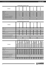
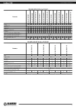
Page 6: ...d air temperature C 25 40 Ingress protection rating of the casing IPX4 SEC class C C C C TECHNICAL DATA OF THE ISO BOX F UNIT Parameters Iso Box F 100 Iso Box F 100 G4 Iso Box F 100 G4 F8 Iso Box F 100 G4 H13 Iso Box F 150 L Iso Box F 150 G4 L Iso Box F 150 G4 F8 L Iso Box F 150 G4 H13 L Iso Box F 150 Iso Box F 150 G4 Iso Box F 150 G4 F8 Iso Box F 150 G4 H13 Iso Box F 200 Iso Box F 200 G4 Iso Box ...

Page 7: ...00 1200 700 1200 700 1200 700 1200 700 1200 700 1200 700 1200 700 1200 700 1200 700 1200 Sound pressure level at 3 m distance dBA 14 23 14 23 14 23 15 25 15 25 15 25 16 27 16 27 16 27 22 38 22 38 22 38 Maximum transported air temperature C 25 40 Ingress protection rating of the casing IPX4 PM 2 5 removal efficiency 35 31 94 93 99 98 31 23 90 87 93 92 47 41 95 94 98 96 37 28 98 97 99 98 SEC class C...

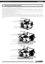
Page 8: ... classes from rough to fine filtering The air flow direction is indicated by the arrow on the fan casing The Iso Box F ES fans are equipped with an electrostatic filter that provides cleaning of air from fine dust aerosols smoke soot particles and soot Electrostatic filters rely on gravity of oppositely charged objects Polluted air flows through the spray charging unit where particles become ioniz...

Page 9: ...ata section Fasteners for unit mounting should be selected by the service technician FAN MOUNTING min 800 mm Nut Washer Vibration absorbing rubber Washer Nut and lock nut Access to filters only for models with filters To get the best performance of the fan and to minimize turbulence induced air pressure losses connect the straight air duct section to the spigots on both sides of the unit while ins...

Page 10: ...cuit breaker installation place must provide quick access for emergency shutdown of the unit The trip current of the automatic circuit breaker QF must exceed the maximum current consumption of the unit refer to the technical data table The recommended trip current of the circuit breaker is the next current in the standard trip current row following the maximum current of the connected unit The aut...

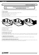
Page 11: ...with a vacuum cleaner 5 Assemble the unit in the reverse order 2 Fan maintenance once a year Even in case of regular maintenance of the filters some dust may accumulate inside the fans and reduce the fan performance and supply air flow Clean the fans with a soft brush or cloth Do not use water aggressive solvents or sharp objects as they may damage the impeller 3 Supply air flow control twice per ...

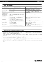
Page 12: ...fan impeller is soiled Clean the impellers The fan or casing screw connection is loose Tighten the screw connection of the fans or the casing all the way Store the unit in the manufacturer s original packaging box in a dry closed ventilated premise with temperature range from 5 С to 40 С and relative humidity up to 70 Storage environment must not contain aggressive vapors and chemical mixtures pro...

Page 13: ... unit the user s manual with the purchase date stamp and the payment paperwork certifying the purchase The unit model must comply with the one stated in the user s manual Contact the Seller for warranty service The manufacturer s warranty does not apply to the following cases User s failure to submit the unit with the entire delivery package as stated in the user s manual including submission with...

Page 14: ...ery with the user s manual The warranty terms are acknowledged and accepted Customer s Signature The Iso Box _______________________________________ unit has been connected to power mains pursuant to the requirements stated in the present user s manual Installation Stamp Seller Address Phone Number Installation Technician s Full Name Installation Date Signature The unit has been installed in accor...

Page 15: ...www blaubergventilatoren de Iso Box F R 15 ...

Page 16: ...www blaubergventilatoren de B163EN 03 ...

Reviews: