background image

www.blaubergventilatoren.de

25

KOMFORT EC S/SB

The 

KOMFORT EC S S15 / KOMFORT EC SB S15

 units are equipped with 

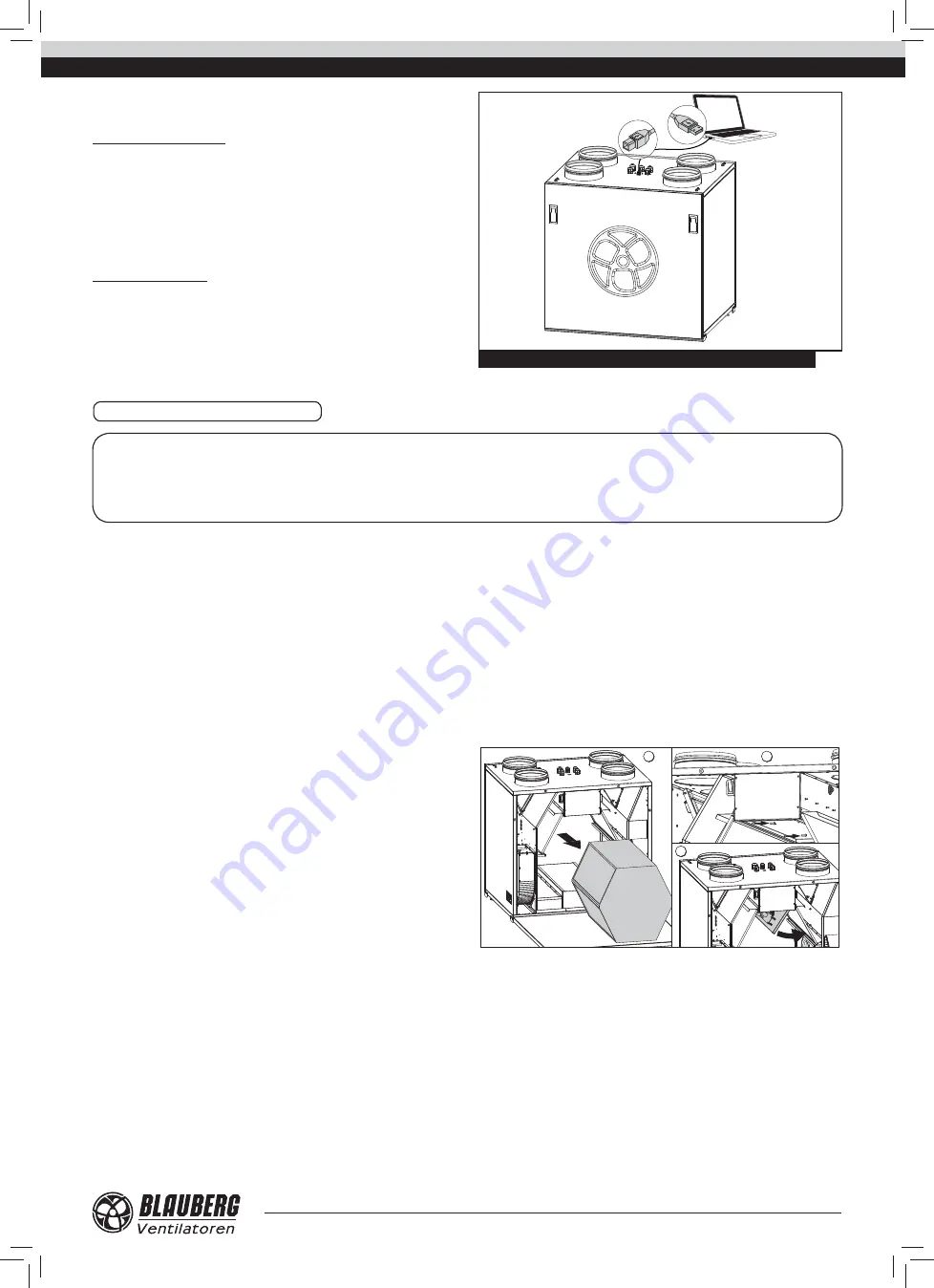
a USB connector (Type B) and can be connected to a PC for confi guring the 
advanced settings in a special software (available for download on the website 
eng.blaubergventilatoren.de). 

To work with the pre-installed software connect the unit to a laptop or 

to a PC via a USB cable with the Type A and Type B contact sockets. The USB 
cable is not included in the delivery set. The software enables editing the unit 
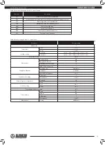
parameters (see Table 10).

The list of the adjustable parameters can be expanded in new versions of 

the software.

Setting, troubleshooting and upgrading of the software version is made by 

the service technician. 

The software is available for downloading on our website: 

blaubergventilatoren.de.

USB Type B

USB Type A

Fig. 21. Connection of a PC to the units with the S15 control panel

TECHNICAL MAINTENANCE 

Regular technical supervision and maintenance of the unit are required to 

ensure the product long service life and non-stop operation.

Disconnect the unit from power supply prior to any maintenance 

operations.

WARNING! Consider the unit sharp edges! Fulfi l  maintenance 

operations in work gloves!

WARNING

Cut power supply to the unit off  by turning the automatic electric switch QF to OFF position prior to 

any maintenance operations.  

Take steps to prevent activation of the automatic switch before fi nishing all the operations.  

The unit must undergo technical maintenance 3 to 4 times a year. 
The unit technical maintenance includes regular cleaning and other works:

1. Filter maintenance (3-4 times per year).

Dirty fi lters increase air resistance in the system and reduce supply air 

volume. The fi lters require cleaning not less than 3-4 times per year. Vacuum 
cleaning is allowed. After two consecutive cleanings fi lters must be replaced. 
For new fi lters contact the Seller. 

2. Heat exchanger maintenance (once a year).

Some dust may accumulate on the heat exchanger block even in case of 

regular maintenance of the fi lters. To maintain the high heat recovery effi

  ciency, 

regular cleaning is required. To clean the heat exchanger pull it out, fl ush the 
heat exchanger with warm detergent solution. After cleaning install the dry 
heat exchanger back to the unit. 

3. Fan maintenance (once a year).

Even in case of regular maintenance of the fi lters, some dust may 

accumulate inside the fans and reduce the fan performance and supply air fl ow. 

Clean the fans with a soft brush or cloth. Do not use water, aggressive 

solvents or sharp objects as they may damage the impeller.

4. Technical maintenance of condensate drainage system (once a year).

The drain pipes may get clogged with the extracted particles. Pour some 

water inside the drain pan to check the pipe for clogging. Clean the U-trap and 
the drain pipe if required.

5. Technical maintenance of an air duct system (every 5 years).

Even regular fulfi lling of all the prescribed above maintenance operations 

may not completely prevent dirt accumulation in the air ducts which reduces 
the unit capacity. Duct maintenance means regular cleaning or replacement. 

6. Control unit maintenance (if necessary).

The control unit maintenance must be performed by an expert qualifi ed for 

unassisted operations with electrical installations with the voltage up to 1000 V 
after careful reading of the user’s manual. 


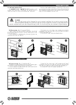
Access to the control board of the control unit:

1

2

3

Summary of Contents for KOMFORT EC S S11/S15 Series

Page 1: ...KOMFORT EC S S11 S15 KOMFORT EC SB S11 S15 HEAT RECOVERY AIR HANDLING UNITS OPERATION MANUAL EN...

Page 2: ...ation and storage regulations 3 Manufacturer s warranty 4 Delivery set 4 Design 5 Operation modes 5 Technical data 7 Unit mounting 12 Condensate drainage 12 Connection to power mains 14 Unit control 2...

Page 3: ...re a trouble free and long service life of the unit TRANSPORTATION AND STORAGE REGULATIONS Transportation of the unit is allowed by any vehicle provided the unit is transported in the original package...

Page 4: ...D indication The units are equipped with an USB connector Type B and can be connected to a PC for configuring the advanced settings in a special software available for download on the website blauberg...

Page 5: ...ry mode Warm extract air from the room flows into the unit and is cleaned in the extract filter Then the air is moved through the heat exchanger and is exhausted outside with the extract fan Cold fres...

Page 6: ...B550 F7 KOMFORT EC S160 S15 FP EC S160 G4 FP EC S160 F7 FS2 KOMFORT EC SB350 S15 FP EC SB350 G4 FP EC SB350 F7 KOMFORT EC SB550 S15 FP EC SB550 G4 FP EC SB550 F7 D1 D L B1 L1 L2 B H H1 Model Dimension...

Page 7: ...on outlet side If the air ducts are too short or not connected protect the unit parts from ingress of foreign objects To prevent uncontrollable access to the fans the spigots may be covered with a pro...

Page 8: ...FS2 HUMIDITY SENSOR MOUNTING Fig 11 The FS2 humidity sensor is not included in the delivery set and can be ordered separately for S15 units The humidity sensor must be installed prior to unit mountin...

Page 9: ...mounting position should enable free access to the removeable service panel for maintenance and service operations INTAKE AIR SUPPLY AIR EXTRACT AIR EXHAUST AIR Left handed modification Right handed m...

Page 10: ...of the equipment 5 Connect the panel to the power supply and set the current date and time S11 CONTROL PANEL MOUNTING The KOMFORT EC S S11 KOMFORT EC SB S11 units have a wall mounted control panel S11...

Page 11: ...g is shown in Fig 15 Connect the control panel to the air handling unit using a supplied connecting cable and fix it to the wall using one of the mounting boxes and the screws Wall flush mounting of t...

Page 12: ...bited and will void the warranty Connect the unit only to power mains with valid electric standards Follow the respective electric standards safety rules DIN VDE 0100 TAB der EVUs The house cabling sy...

Page 13: ...he contact is closed the unit turns to the maximum speed FS2 U 0 10V GND humidity sensor connection Connect the FS2 humidity sensor not included in the delivery set can be ordered separately to the co...

Page 14: ...status indicator is displayed the unit is connected to network the unit is disconnected from network 2 Unit activation and deactivation The unit is activated with ON button Press OFF for the unit deac...

Page 15: ...level is set via the Engineering menu see clause 14 If the AUTO or TIMER mode is activated the current air flow value is displayed in real time operation no matter of the set air flow value Set the r...

Page 16: ...acement periodicity EXIT return to the Main menu 6 Engineering menu To enter the Engineering menu press ENG MENU in the User menu To access the Engineering menu enter the password The default setting...

Page 17: ...ed with a rectangle Use or buttons to set the air flow value for each fan speed stage The air flow is set as a percentage of the maximum performance of each fan To return to the Engineering menu witho...

Page 18: ...operation mode set 1 in the BYPASS OPERATION MODE to select the regular operation mode which prevents heat exchanger freezing or 2 to enable bypass opening in the ventilation mode To save the changes...

Page 19: ...TER to confirm To return to the Engineering menu without saving changes press EXIT 14 Humidity setting Select the HUMIDITY SETTING item in the Engineering menu and press ENTER Select the humidity sens...

Page 20: ...ering menu without saving changes press EXIT The default settings are given in Table 8 18 Current temperature review To review the current temperatures select the CURRENT TEMPERATURES submenu from the...

Page 21: ...ff between the operating periods To return to the Engineering menu and save changes automatically press EXIT 20 Timer To activate the timer press TIMER in the control panel Main menu To set up the tim...

Page 22: ...sed from the filter installation Press RESET after replacement of the filter To save the changes and return to the Engineering menu press EXIT 22 Errors The control panel displays the following messag...

Page 23: ...sensor actuation Parameter Factory setting Air flow rate 1 Temperature Duct 25 C Room 20 C Air flow setting Air supply Speed 1 40 Speed 2 70 Speed 3 99 Air extract Speed 1 40 Speed 2 70 Speed 3 99 Te...

Page 24: ...once When the touch button is activated the display lights up and the unit switches to the Summer Cooling mode in one of the ways depending on the unit model KOMFORT EC SB350 S15 and KOMFORT EC SB550...

Page 25: ...intenance 3 4 times per year Dirty filters increase air resistance in the system and reduce supply air volume The filters require cleaning not less than 3 4 times per year Vacuum cleaning is allowed A...

Page 26: ...dampers the supply diffusers or the exhaust grilles are closed or soiled Open and clean the air dampers the supply diffusers the exhaust grilles to ensure free air flow Cold supply air The extract fi...

Page 27: ...of the Member States relating to electromagnetic compatibility which relate to electrical appliances used in set voltage classes This certificate is issued following test carried out on samples of th...

Page 28: ...www blaubergventilatoren de KOMFORT EC S SB v 3 5 4 EN...

Reviews: