background image

www.blaubergventilatoren.de

3

KOMFORT EC S/SB

BLAUBERG Ventilatoren GmbH

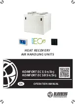
 Company is happy to off er  your 

attention a heat recovery air handling unit KOMFORT EC S/SB.  

INTRODUCTION

The present operation manual contains a technical description, technical 

data sheets, operation and mounting guidelines, safety precautions and 
warnings for safe and correct operation of the unit.

Read carefully and understand the operation manual, especially the 

safety requirements, before the unit mounting and start up.

Keep the operation manual available as long as you use the unit.

GENERAL

The heat recovery air handling unit KOMFORT EC S/SB is designed for 

effi

  cient and energy saving ventilation of domestic and public premises.

The unit is not a ready to use product but a component part of central air 

conditioning and ventilation network.

The unit is designed for suspended mounting.
The unit is designed for indoor application with the ambient temperature 

ranging from +1 °C up to +40 °C and relative humidity up to 80 %. 

Hazardous parts access and water ingress protection rating:


unit motors - IP 44;


assembled unit connected to air ducts - IP 22.

The unit design is regularly improved, so some models can slightly diff er 

from those ones described in this operation manual.

SAFETY REGULATIONS

All operations related to the unit electrical connections, servicing and 

repair works are allowed only after the unit is disconnected from power 
supply.

All mounting and servicing operations are allowed by duly qualifi ed 

personnel.

Please, follow the safety regulations and working instructions (DIN EN 50 

110, IEC 364).

Make sure the impeller and the casing are not damaged before connecting 

the unit to power supply. The casing internals must be free of any foreign 
objects which can damage the impeller blades or the motor.

The appliance maintenance and repair is allowed only after power cut-off  

and full stop of the rotating parts.

Misuse of the unit or any unauthorized modifi cation are not allowed.
The appliance is designed for connection to power supply in compliance 

with the «Technical data» section. 

The unit is rated for permanent operation. 
Take steps to prevent ingress of smoke, carbon monoxide and other 

combustion products into the room through open chimney fl ues or other 
fi re-protection devices. Suffi

  cient air supply must be provided for proper 

combustion and exhaust of gases through the chimney of fuel burning 
equipment to prevent back drafting. The maximum permitted pressure 
diff erence per living units is 4 Pa. 

The transported air must not contain any dust or other solid impurities, 

sticky substances or fi brous materials. 

The appliance is not rated for operation in a fl ammable or explosive 

medium. 

Fulfi l the operation manual requirements to ensure a trouble-free and 

long service life of the unit.

TRANSPORTATION AND STORAGE REGULATIONS

Transportation of the unit is allowed by any vehicle provided the unit is 

transported in the original package and is protected against weather and 
mechanical damages. 

Use hoist machinery for handling and transportation to prevent possible 

mechanical damages of the unit. Fulfi l the requirements for transportation of 
the specifi ed cargo type during cargo-handling operations.

Store the unit in a dry and cool place in the original packing. 
The storage environment must not be subjected to any aggressive and/

or chemical evaporations, admixtures, foreign objects that may provoke 
corrosion and damage connection tightness.

Store the unit in an environment with minimized risk of mechanical 

damages, temperature and humidity fl uctuations.

Do not expose the unit to the temperatures below  +5 °C and above  +40 °C . 
Connection of the unit to power supply is allowed after the appliance has 

been kept indoors for minimum two hours.

MANUFACTURER’S WARRANTY

The unit complies with the requirements according to the EU norms 

and directives, to the relevant EU-Low Voltage Equipment Directives, EU-
Directives on Electromagnetic Compatibility.

We hereby declare that the unit complies with the essential protection 

requirements of Electromagnetic Council Directive 2004/108/EC, 89/336/EEC 
and Low Voltage Directive 2006/95/EC, 73/23/EEC and CE-marking Directive 
93/68/EEC on the approximation of the laws of the Member States relating 
to electromagnetic compatibility, which relate to electrical appliances used 
in set voltage classes.

The manufacturer hereby warrants normal operation of the unit over the 

period of two years from the retail purchase date provided observance of the 
installation and operation regulations.

In case of a failure due to a manufacturing fault during the warranty 

period the consumer has the right to exchange it.

The replacement is off ered by the Seller.
In case of no confi rmation of the purchase date, the warranty period shall 

be calculated from the manufacturing date.

The MANUFACTURER is not responsible for any damage resulting from 

any misuse of or gross mechanical interference with the unit.

The MANUFACTURER is not responsible for the damages resulted due to 

the use of  third party equipment or to third party equipment.  


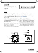
                 WARNING


The unit contains in part materials that can be 

recycled and in part substances that should not end up 
as domestic waste.

Dispose of the unit once it has reached the end of its 

working life according to the regulations valid in your 
country. 


                  WARNING 


The unit is not allowed for use by children and persons with reduced 

physical, mental or sensory capacities, without proper practical experience 
or expertise, unless they are controlled or instructed on the product opera-
tion by the person(s) responsible for their safety. 

Supervise the children and do not let them play with the product. 
 

!

Summary of Contents for KOMFORT EC S S11/S15 Series

Page 1: ...KOMFORT EC S S11 S15 KOMFORT EC SB S11 S15 HEAT RECOVERY AIR HANDLING UNITS OPERATION MANUAL EN...

Page 2: ...ation and storage regulations 3 Manufacturer s warranty 4 Delivery set 4 Design 5 Operation modes 5 Technical data 7 Unit mounting 12 Condensate drainage 12 Connection to power mains 14 Unit control 2...

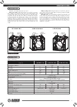
Page 3: ...re a trouble free and long service life of the unit TRANSPORTATION AND STORAGE REGULATIONS Transportation of the unit is allowed by any vehicle provided the unit is transported in the original package...

Page 4: ...D indication The units are equipped with an USB connector Type B and can be connected to a PC for configuring the advanced settings in a special software available for download on the website blauberg...

Page 5: ...ry mode Warm extract air from the room flows into the unit and is cleaned in the extract filter Then the air is moved through the heat exchanger and is exhausted outside with the extract fan Cold fres...

Page 6: ...B550 F7 KOMFORT EC S160 S15 FP EC S160 G4 FP EC S160 F7 FS2 KOMFORT EC SB350 S15 FP EC SB350 G4 FP EC SB350 F7 KOMFORT EC SB550 S15 FP EC SB550 G4 FP EC SB550 F7 D1 D L B1 L1 L2 B H H1 Model Dimension...

Page 7: ...on outlet side If the air ducts are too short or not connected protect the unit parts from ingress of foreign objects To prevent uncontrollable access to the fans the spigots may be covered with a pro...

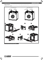
Page 8: ...FS2 HUMIDITY SENSOR MOUNTING Fig 11 The FS2 humidity sensor is not included in the delivery set and can be ordered separately for S15 units The humidity sensor must be installed prior to unit mountin...

Page 9: ...mounting position should enable free access to the removeable service panel for maintenance and service operations INTAKE AIR SUPPLY AIR EXTRACT AIR EXHAUST AIR Left handed modification Right handed m...

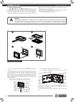
Page 10: ...of the equipment 5 Connect the panel to the power supply and set the current date and time S11 CONTROL PANEL MOUNTING The KOMFORT EC S S11 KOMFORT EC SB S11 units have a wall mounted control panel S11...

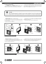
Page 11: ...g is shown in Fig 15 Connect the control panel to the air handling unit using a supplied connecting cable and fix it to the wall using one of the mounting boxes and the screws Wall flush mounting of t...

Page 12: ...bited and will void the warranty Connect the unit only to power mains with valid electric standards Follow the respective electric standards safety rules DIN VDE 0100 TAB der EVUs The house cabling sy...

Page 13: ...he contact is closed the unit turns to the maximum speed FS2 U 0 10V GND humidity sensor connection Connect the FS2 humidity sensor not included in the delivery set can be ordered separately to the co...

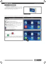
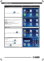
Page 14: ...status indicator is displayed the unit is connected to network the unit is disconnected from network 2 Unit activation and deactivation The unit is activated with ON button Press OFF for the unit deac...

Page 15: ...level is set via the Engineering menu see clause 14 If the AUTO or TIMER mode is activated the current air flow value is displayed in real time operation no matter of the set air flow value Set the r...

Page 16: ...acement periodicity EXIT return to the Main menu 6 Engineering menu To enter the Engineering menu press ENG MENU in the User menu To access the Engineering menu enter the password The default setting...

Page 17: ...ed with a rectangle Use or buttons to set the air flow value for each fan speed stage The air flow is set as a percentage of the maximum performance of each fan To return to the Engineering menu witho...

Page 18: ...operation mode set 1 in the BYPASS OPERATION MODE to select the regular operation mode which prevents heat exchanger freezing or 2 to enable bypass opening in the ventilation mode To save the changes...

Page 19: ...TER to confirm To return to the Engineering menu without saving changes press EXIT 14 Humidity setting Select the HUMIDITY SETTING item in the Engineering menu and press ENTER Select the humidity sens...

Page 20: ...ering menu without saving changes press EXIT The default settings are given in Table 8 18 Current temperature review To review the current temperatures select the CURRENT TEMPERATURES submenu from the...

Page 21: ...ff between the operating periods To return to the Engineering menu and save changes automatically press EXIT 20 Timer To activate the timer press TIMER in the control panel Main menu To set up the tim...

Page 22: ...sed from the filter installation Press RESET after replacement of the filter To save the changes and return to the Engineering menu press EXIT 22 Errors The control panel displays the following messag...

Page 23: ...sensor actuation Parameter Factory setting Air flow rate 1 Temperature Duct 25 C Room 20 C Air flow setting Air supply Speed 1 40 Speed 2 70 Speed 3 99 Air extract Speed 1 40 Speed 2 70 Speed 3 99 Te...

Page 24: ...once When the touch button is activated the display lights up and the unit switches to the Summer Cooling mode in one of the ways depending on the unit model KOMFORT EC SB350 S15 and KOMFORT EC SB550...

Page 25: ...intenance 3 4 times per year Dirty filters increase air resistance in the system and reduce supply air volume The filters require cleaning not less than 3 4 times per year Vacuum cleaning is allowed A...

Page 26: ...dampers the supply diffusers or the exhaust grilles are closed or soiled Open and clean the air dampers the supply diffusers the exhaust grilles to ensure free air flow Cold supply air The extract fi...

Page 27: ...of the Member States relating to electromagnetic compatibility which relate to electrical appliances used in set voltage classes This certificate is issued following test carried out on samples of th...

Page 28: ...www blaubergventilatoren de KOMFORT EC S SB v 3 5 4 EN...

Reviews: