www.blaubergventilatoren.de
KoMFort Erv d
11
DISCONNECT THE UNIT FROM POWER SUPPLY BEFORE
ANY MAINTENANCE OPERATIONS!
TECHNICAL MAINTENANCE
The unit must undergo technical maintenance 3 to 4 times a year.
They include general cleaning of the unit and the following operations:
1. Filter maintenance (3-4 times per year).
Dirty filters increase air resistance in the system and reduce supply air volume.
Replace the filters not less than 3-4 times per year.
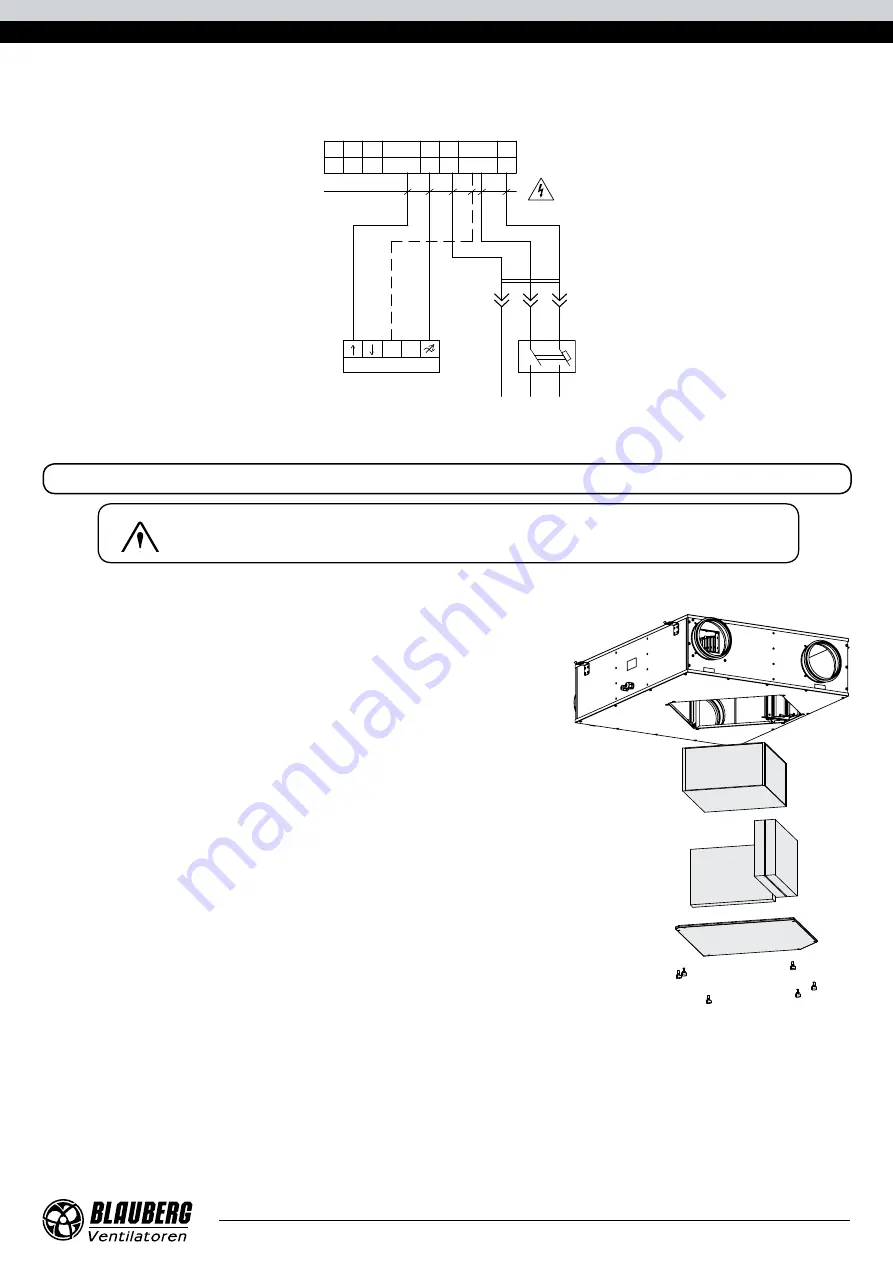
To replace the filters, remove the inspection hatch located on the service panel and
remove the dirty filters, then install the new filters and the inspection hatch in the
reverse order. For new filters, contact the Seller.
2. Heat exchanger maintenance (once a year).
Some dust may accumulate on the heat exchanger block even in case of regular
maintenance of the filters. To maintain high heat exchange efficiency, periodical dry
cleaning is recommended. Use a vacuum cleaner with a narrow nozzle.
To replace the heat exchanger, remove the inspection hatch located on the service
panel and remove the contaminated heat exchanger
Then install a new heat exchanger and an inspection hatch in the reverse order.
For a new heat exchanger contact the Seller.
3. Fan maintenance (once a year).
Even in case of regular maintenance of the filters, some dust may accumulate inside
the fans and reduce the fan performance and supply air flow.
Clean the fans with a soft brush or cloth. Do not use water, aggressive solvents or
sharp objects as they may damage the impeller.
4. Technical maintenance of air duct system (every 5 years).
Even regular fulfilling of all the prescribed above maintenance operations may not completely prevent dirt accumulation in the air
ducts which reduces the unit capacity. Duct maintenance means regular cleaning or replacement.
5. Control unit maintenance (if necessary).
The control unit is positioned inside the unit casing.
For accessing the control unit remove the fixing screws on the service panel and remove it.
L
N
PE
QF
Х
1
8
5
7 6
5
4 3
2
1
4 3
2
1 PE
N
L
N N
L
N
PE
QF
Wiring diagram
(unit with an S20 controller)


