www.blaubergventilatoren.de
KoMFort Erv d
7
DESIGN AND OPERATING PRINCIPLE
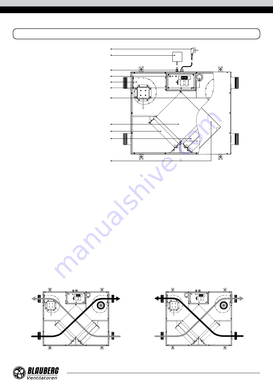
Supply fan
Extract fan
Extract air filter
Control unit
Thermostat for heat exchanger freeze protection
Cable glands
Cross-flow heat exchanger
Supply air filter
Controller
Power cord with a plug
Inspection hatch for filter and heat
exchanger maintenance
The service side of the unit is equipped with a detachable inspection hatch on manual bolts for filter and heat exchanger cleaning and
replacement operations. The plate enthalpy cross-flow heat exchanger is made of polymerized cellulose.
The control unit is positioned inside the unit casing . The power cable and grounding cables are connected to the control unit via the
cable gland located at the side of the unit. The unit is equipped with a controller and a power cord with a Euro Plug XP.
Warm stale extract air from the room flows into the unit, where it is filtered by the extract filter, then air flows through the heat
exchanger and is exhausted outside by the extract fan. Cold fresh air from the outside flows into the unit, where it is cleaned by the
supply filter. Then the air flows through the heat exchanger and is directed to the room with the supply fan.
Supply air is heated in the heat exchanger by transferring the heat energy of warm and humid extract air to the cold fresh air.
The air flows are fully separated while flowing through the heat exchanger. Heat recovery minimizes heat losses, which reduces the
cost of space heating in the cold season. The enthalpy heat exchanger provides both heat and humidity recovery.
In warm seasons the heat exchanger operates to cool down and dehumidify the supply air. In cold seasons the heat exchanger
operates to warm up supply air and humidify it. Water vapour from the humid extract air is condensed and absorbed by the heat
exchanger plates. The recovered humidity and heat are transferred to the supply air flow. The air streams are fully separated within the
heat exchanger and the microbes and smells are isolated.
LEFT-HANDED AND RIGHT-HANDED MODIFICATIONS
The figure below shows the arrangement of spigots for left- and right-handed modifications. Choosing the right arrangement can
improve the ease of installation, shorten the length of the ducts and reduce the number of air duct bends (elbows)
R
EXTRACT AIR
SUPPLY AIR
INTAKE AIR
EXHAUST AIR
INTAKE AIR
SUPPLY AIR
EXHAUST AIR
EXTRACT AIR
Left-handed modification
Right-handed modification
Left-handed modification


