background image

www.blaubergventilatoren.de

KoMFort roto ec S2(e)200

12

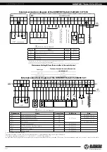
External connections diagram of the KOMFORT Roto EC S2(E)200  S17/S18

2

1

L

SM1*

N

Connection of sensors  with 0-10 V analogue  output

Normally opened contact  from relay sensor or switch

Condenser unit activation  signal (no-contact, 16 A)

Power input 

230 VAC

2

1

PK1*

1

Х1

Control unit

Х4

gnd

2

R+

3

R-

4

GND~

5

~24V

6

0-10V

7

GND

8

~24V

9

NO

10

NO

11

NO

12

NO

13

2

14

1

15

2

16

1

17 18

N

19

L1

GND

Green

Yellow

Brown

Grey

White

P1**    th-Tune

Rx+/Tx+

Rx-/Tx-

GND

~

~24V

1

TS1

2

TS1

3 4

N

5

L

Grey

Black

Yellow/green

Blue

Brown

P2*

    Kitchen hood

TS1

1

2

1

2

HL1

PE

 Electric shock hazard!

Design. 

Name

Model

Wire**

SM1*

Exhaust or supply air damper electric actuator 

LF230

2x0.75 mm

2

PK1*

Contact from fire alarm panel

NC

2x0.75 mm

2

P1*

Control panel

th-Tune

P2*

Kitchen hood

*The appliances are not supplied with the unit, are available on the separate order. 
**Wire cross-section at a cable length of maximum 100 m.

Maximum cable length from the controller to the control panel

Cable type

Distance between the controller and the 

control panel

Phone cable

up to 50 m

AWG24 shielded cable

up to 200 m

External connections diagram of the  KOMFORT Roto EC S2(E)200  S21

XS11

X1

1

C

2

NC

3 4

N

5

L

Grey

Black

Yellow/green

Blue

Brown

KH1*


TS1

1

2

1

2

HL

PE

GND

GND 0-10V

A

B

+24V

+24V

1

2

PK1*

1

2

1

2

1

2

1

2

Boost*

CO2*

P1*

SM1*

SM2*

1

2

C

C

U

1

2

1

2

**U

**U

L

N
N

NC C

PE

L1

C

NO

NO

NO

C

C

C

A B

0-10V +24V

+24V

NO

GND

GND

1     2      3      4       5       6       7      8      9      10    11    12     13   14    15    16      17 

Po

wer supply

230 

V/50 (60) H

z

Brown

Yello

w

Gr

een

W

hit

e


Electric shock hazard!

Designation

Name

Contact type

Cable type

Note

SМ1*

Supply air damper actuator

NO

2 x 0,75 mm

2

3A, 30DC/~250 AC

SМ2 *

Extract air damper actuator

NO

3A, 30DC/~250 AC

РК1*

Contact from fire alarm panel

NC

CCU*

CCU control

NO

3A, 30DC/~250 AC

Р1*

External control panel

4 x 0,25 mm

2

Boost*

On/Off contacts of the Boost mode

NO

2 x 0,75 mm

2

CO2*

Outdoor CO

2

 sensor

3 x 0,25 mm

2

KH*

Kitchen hood

5 x 0,75 mm

2

*Is not included in the delivery set.
*The supply voltage U of the SM1, SM2 external dampers  is selected depending on the type of dampers.
*** Output parameters: terminals 12-17 - 3 A, 30VDC / ~ 250VAC (“dry contact”).
The maximum cable length from external devices to the terminal block should not exceed 100 meters. The recommended cable cross-section is shown in the table.

Summary of Contents for KOMFORT Roto EC S2 200

Page 1: ...Heat recovery air handling unit USER S MANUAL EN KOMFORT Roto EC S2 200 KOMFORT Roto EC S2E200...

Page 2: ...on of its products at any time in order to incorporate the latest technological developments No part of this publication may be reproduced stored in a retrieval system or transmitted in any form or by...

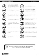
Page 3: ...r Protect the electric parts of the unit against ingress of water Do not allow children to operate the unit Disconnect the unit from power mains prior to any technical maintenance Do not store any exp...

Page 4: ...ain any flammable or explosive mixtures evaporation of chemicals sticky substances fibrous materials coarse dust soot and oil particles or environments favourable for the formation of hazardous substa...

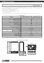
Page 5: ...ineral wool Filter extract G4 supply G4 F7 Connected air duct diameter mm 125 Weight kg 47 48 Heat recovery efficiency from 75 up to 92 Heat exchanger type rotary Heat exchanger material aluminium SEC...

Page 6: ...hood The kitchen hood must be equipped with an air damper to shut off the exhaust duct when the kitchen hood is not in use Unit design and operation principle service side view Intake filter Extract...

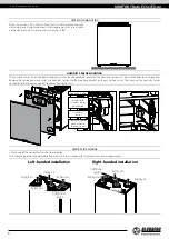
Page 7: ...able access to the fan the spigots may be covered with a protecting grille or other protecting device with mesh width not more than 12 5 mm While installing the unit ensure convenient access for subse...

Page 8: ...and install the humidity sensor into the mounting bracket on the exhaust duct wall Then connect the humidity sensor connector to the respective contact socket on the control unit 1 2 3 Contact socket...

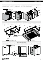
Page 9: ...the unit for floor mounting Then undo the four self tapping screws and remove the plug in the bottom panel Lead the kitchen hood cable into the unit and connect it according to the external connection...

Page 10: ...on selection must be based on the maximum load current maximum conductor temperature depending on the wire type insulation length and installation method The external power input must be equipped with...

Page 11: ...connector for the kitchen hood X4 is located on the side wall of the unit It is necessary to lead the cable into the unit and connect it to the connector according to the wiring diagram For right han...

Page 12: ...and the control panel Phone cable up to 50 m AWG24 shielded cable up to 200 m External connections diagram of the KOMFORT Roto EC S2 E 200 S21 XS11 X1 1 C 2 NC 3 4 N 5 L Grey Black Yellow green Blue B...

Page 13: ...ncy regular cleaning is required To clean the heat exchanger remove it from the unit and clean the heat exchanger by using compressed air or a vacuum cleaner After cleaning re install the heat exchang...

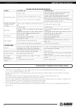
Page 14: ...air duct pipe flanges Install anti vibration connectors SYSTEM ALARMS Fire alarm Emergency system shutdown on command from the fire alarm board This alarm interrupts the fan operation In case of such...

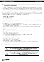
Page 15: ...air the user must provide the unit the user s manual with the purchase date stamp and the payment paperwork certifying the purchase The unit model must comply with the one stated in the user s manual...

Page 16: ...www blaubergventilatoren de KOMFORT Roto EC S2 E 200 16...

Page 17: ...www blaubergventilatoren de KOMFORT Roto EC S2 E 200 17...

Page 18: ...www blaubergventilatoren de KOMFORT Roto EC S2 E 200 18...

Page 19: ...__200 S___ unit is installed pursuant to the requirements stated in the present user s manual Installation Stamp Company name Address Phone Number Installation Technician s Full Name Installation Date...

Page 20: ...www blaubergventilatoren de B140 1EN 04...

Reviews: