background image

15

EXTERNAL CONNECTION DIAGRAM FOR S2 AUTOMATION SYSTEM

EXTERNAL CONNECTIONS DIAGRAM FOR S12 AUTOMATION SYSTEM

1

2

3

5

8

6

7

4

L

N

PE

+10V

CTR

GND

L

N

PE

+10V

CTR

GND

+10V

48V

CTR

GND

Power supply 

230 V/ 50/60 Hz

QF

XP

8

7

6

4

1

3

2

5

5

4

3

1

N

PE

5

L

L

4

3

1

N

2

2

PE

In

Out1

Power supply 

230 V/ 50/60 Hz

QF

XP

Summary of Contents for Komfort Ultra EC L 300-E S14

Page 1: ...L Komfort Ultra EC L 300 H E S2 Komfort Ultra EC S 300 H E S2 Komfort Ultra EC L 300 H E S14 Komfort Ultra EC S 300 H E S14 Komfort Ultra L 250 H E S12 Komfort Ultra S 250 H E S12 Heat recovery air ha...

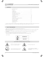
Page 2: ...er s manual consisting of the technical details operating instructions and technical specification covers the installation and mounting of the Komfort Ultra S L 350 H E heat recovery air handling unit...

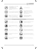
Page 3: ...lectric parts of the unit against ingress of water UNIT MOUNTING AND OPERATION SAFETY PRECAUTIONS Do not allow children to operate the unit Disconnect the unit from power mains prior to any technical...

Page 4: ...CHILDREN The unit is designed for floor and suspended mounting The unit is rated for continuous operation Transported air must not contain any flammable or explosive mixtures evaporation of chemicals...

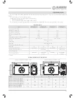
Page 5: ...2700 Sound pressure level at 3 m distance dB A 28 47 28 47 Transported air temperature o C from 25 to 60 from 25 to 40 Insulation 20 mm mineral wool Extract filter G4 Intake filter G4 F8 PM2 5 81 Con...

Page 6: ...H E Komfort Ultra EC L 250 300 H E QWDNH DLU OWHU ZLWK KLJKHU OHYHO RI OWHULQJ Supply fan Drain pan KDXVW IDQ Drain pipe WUDFW OWHU Humidity sensor option for S14 automation system Extract air tempera...

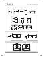
Page 7: ...are too short or not connected protect the unit parts from ingress of foreign objects To prevent uncontrollable access to the fans the spigots may be covered with a protecting grille or other protect...

Page 8: ...fixing screws on the mounting brackets Ceiling mounting using mounting brackets Wall mounting using mounting brackets SUSPENDED MOUNTING USING L SHAPED BRACKETS When using the L shaped brackets the u...

Page 9: ...midity sensor Mount SERVICE SIDE CHANGE Make sure of the correct unit service side selection Unit mounting position should enable free excess to the service panel for maintenance and service operation...

Page 10: ...mfort Ultra EC S 250 300 H E air handling unit The procedure of the service side changing for Komfort Ultra EC L 250 300 H E is carried out in the same manner CONDENSATE DRAINAGE SYSTEM CONNECTION The...

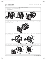
Page 11: ...of the control panel and remove the back cover 3 Fix the back side of the casing to the mounting box through the mounting holes then connect the cable to the control panel in accordance with the Wiri...

Page 12: ...t the control cable from the speed controller Remember the colour marking of the wires and the terminals to enable their correct connection after completing of the speed controller mounting Screws 3 I...

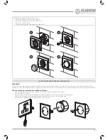
Page 13: ...peed controller onto an uneven surface While tightening the self tapping screws do not apply excessive force to prevent speed controller casing deformation The sensor speed controller is installed as...

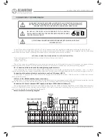
Page 14: ...hing system contact remove the jumper between the terminals 1 and 2 In case of fire the normally closed dry contact breaks the control circuit from the central fire fighting board and cuts off power s...

Page 15: ...EM EXTERNAL CONNECTIONS DIAGRAM FOR S12 AUTOMATION SYSTEM 1 2 3 5 8 6 7 4 L N PE 10V CTR GND L N PE 10V CTR GND 10V 48V CTR GND Power supply 230 V 50 60 Hz QF XP 8 7 6 4 1 3 2 5 5 4 3 1 N PE 5 L L 4 3...

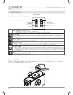
Page 16: ...the required speed Speed changeover Press the inactive speed setting button once The selected button will be highlighted and the unit will switch to the required speed Unit deactivation To turn the un...

Page 17: ...S2 AUTOMATION SYSTEM CONTROL OF THE UNIT WITH THE S12 AUTOMATION SYSTEM The unit is operated from the sensor speed controller by using the touch buttons Operation Button When the system is powered on...

Page 18: ...t may accumulate on the heat exchanger block even in case of regular maintenance of the filters To maintain the high heat recovery efficiency regular cleaning is required To clean the heat exchanger p...

Page 19: ...19 1 2 3 4 TECHNICAL MAINTENANCE OF THE UNIT...

Page 20: ...go type while loading and unloading Use any vehicle types for the unit transportation provided that it is protected against mechanical or weather damage Avoid any mechanical shocks and strokes during...

Page 21: ...one Number E mail Purchase Date Seller s Stamp Seller s Stamp Seller s Stamp This is to certify acceptance of the complete unit delivery with the user s manual The warranty terms are acknowledged and...

Page 22: ...www blaubergventilatoren de 22 Komfort Ultra EC L S 250 300 H E...

Page 23: ...23...

Page 24: ...Komfort_Ultra EC _S L _300 250 _v 2 0 _EN...

Reviews: