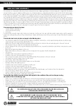
CONNECTION TO POWER MAINS
DISCONNECT THE POWER SUPPLY PRIOR TO ANY OPERATIONS WITH THE UNIT.
CONNECTION OF THE UNIT TO POWER MAINS IS ALLOWED BY A QUALIFIED
ELECTRICIAN WITH A WORK PERMIT FOR THE ELECTRIC UNITS UP TO 1000 V AFTER
CAREFUL READING OF THE PRESENT USER’S MANUAL.
THE RATED ELECTRICAL PARAMETERS OF THE UNIT ARE GIVEN ON THE
MANUFACTURER’S LABEL.
ANY TAMPERING WITH THE INTERNAL CONNECTIONS IS PROHIBITED
AND WILL VOID THE WARRANTY.
• The unit is rated for connection to 3~400 V 50 Hz power mains according to the wiring diagram.
• The connection must be made using durable, insulated and heat-resistant conductors (cables, wires). The actual wire cross section
selection must be based on the maximum load current, maximum conductor temperature depending on the wire type, insulation,
length and installation method.
• Connection of the unit to the fixed power supply network must be carried out in accordance with the current regulations.
Caution! The type of electrical connection is indicated in the technical data table.
Wiring diagram
L1
X1
L1
L1
L1
L2
L3
PE
~400 V/50 Hz
Connect the cables to the terminal block incorporated inside the terminal box located on the fan casing in compliance with the fan
wiring diagram and the terminal designation. The terminal designations are shown on the label inside the fan casing.
The electric parameters of the fan are shown on the label on the fan casing.
The fan motor is not equipped with an integrated thermal protection.
Consider that while selecting a starter or a closing relay.
MAKE SURE THAT THE FAN IMPELLER ROTATES IN THE DIRECTION MARKED BY THE
ARROW ON THE FAN CASING.
IF NECESSARY, CHANGE THE IMPELLER ROTATION DIRECTION BY ALTERING THE PHASE
SEQUENCE ON THE ELECTRIC MOTOR TERMINALS.
www.blaubergventilatoren.de
tower-sV-k2
11


