background image

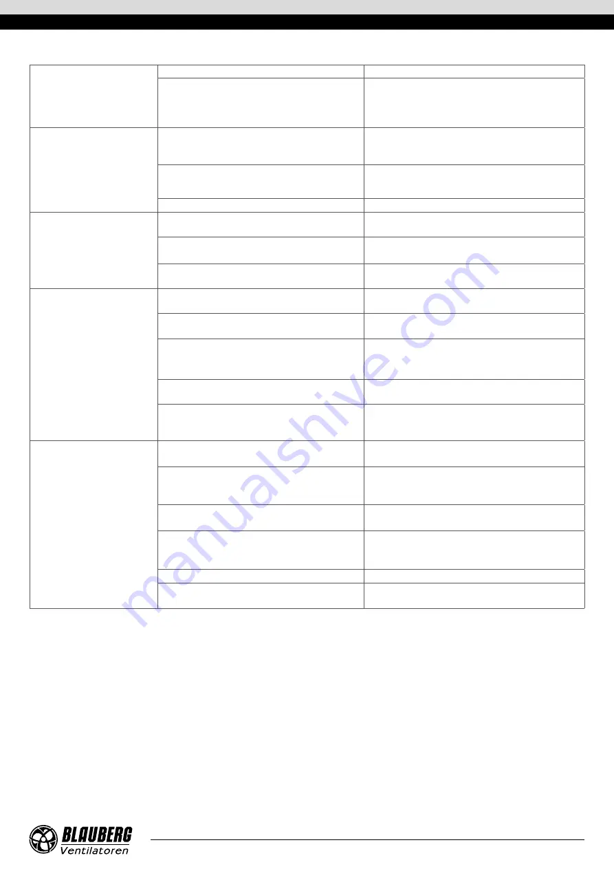
The fan fails to reach the 

required rotation speed due to 

serious overheating of the fan 

motor.

Fan motor overloaded.

Eliminate the overload.

Improper fan starting method.

Use a soft starter or frequency converter to start the motor 

(see “Asynchronous Electric Motor Starting Methods” 

in the “Connection to power mains” section)

.

The fan motor runs at 

overload capacity with current 

consumption in excess of the 

rated value.

The fan supplies more air than expected upon motor 

capacity selection.

Measure network resistance. Throttle down the network 

(add aerodynamic resistance to the air duct network).

Wrong motor phasing. The impeller rotates in the 

opposite direction of the arrow on the fan casing.

If necessary, change the impeller rotation direction by 

changing the phase sequence on the electric motor 

terminals.

Air ducts clogged.

Clean the air duct or the impeller.

The fan supplies more air than 

expected.

The resistance values used during the ventilation 

network calculations are too conservative.

Check the air ducts for proper shape and cross section as 

well as for any dampers present.

The cross section of air ducts increased and their 

number reduced during the installation.

Throttle down the network (add aerodynamic resistance 

to the air duct network).

Wrong choice of the fan.

Replace the fan with a unit of proper standard size.

The fan supplies less air than 

expected.

Wrong calculation of the ventilation network and 

wrong selection of the fan.

Re-calculate the network parameters and select a 

matching fan.

The network resistance exceeds the design 

calculations.

Re-arrange the ventilation network to decrease its 

aerodynamic resistance.

Wrong direction of the impeller rotation.

If necessary, change the impeller rotation direction by 

changing the phase sequence on the electric motor 

terminals 

(see the “Commissioning” section)

.

Air leak through a loose air duct connection.

Eliminate the air leak. Seal the air duct connection.

Impeller or air duct contamination with foreign 

objects or debris.

Clean the impeller or the air ducts from foreign objects or 

debris.

Excessive noise or vibration both 

inside the fan and in the circuit.

Loose screw connections.

Check the screw connections for proper tightness.

No flexible joints between the fan and the ventilation 

network on the suction and discharge sides.

Install flexible joints.

Loose connection of valves and dampers to the air 

ducts.

Tighten up the fasteners of valves and dampers.

Impeller or air duct contamination with foreign 

objects or debris.

Clean the impeller or the air ducts from foreign objects or 

debris.

Worn bearings.

Replace the bearings.

Unstable power supply, unstable motor operation.

Check the stability of power supply parameters and 

electric motor operation.

www.blaubergventilatoren.de

tower-sV-k2

15

Summary of Contents for Tower-SV-K2

Page 1: ...Roof mounted centrifugal smoke extraction fan USER S MANUAL EN Tower SV K2...

Page 2: ...al and national construction electrical and technical norms and standards must be observed when installing and operating the unit Disconnect the unit from the power supply prior to any connection serv...

Page 3: ...ck of experience and knowledge unless they have been given supervision or instruction concerning use of the unit by a person responsible for their safety Children should be supervised to ensure that t...

Page 4: ...nditions The fan handles smoke and air mixtures with temperatures up to 600 C for 60 minutes A characteristic feature of Tower SV K2 roof fans is an impeller with backward curved blades and an electri...

Page 5: ...U1 temperate climate HL1 cold climate T1 tropical climate M1 marine moderately cold climate Options K with a terminal box S1 built in external switch 1 5 motor power kW Motor phase and operation mode...

Page 6: ...0 75 2 15 910 8500 Tower SV K2 560 4D 3 X XX 600 2 XXX 3 0 6 48 1420 13000 Tower SV K2 630 8D 0 75 X XX 600 2 XXX 0 75 2 64 700 9000 Tower SV K2 630 6D 1 5 X XX 600 2 XXX 1 50 3 84 940 12500 Tower SV...

Page 7: ...Overall dimensions B A C H d 4 holes www blaubergventilatoren de Tower SV K2 7...

Page 8: ...0 75 K U1 600 2 Zn 1060 1010 750 1121 16 Tower SV K2 630 6D 1 5 K U1 600 2 Zn Tower SV K2 630 4D 5 5 K U1 600 2 Zn Tower SV K2 710 8D 1 1 K U1 600 2 Zn 1105 1180 980 1257 16 Tower SV K2 710 6D 2 2 K U...

Page 9: ...m the fan The fan delivery set may include a mounting frame available separately Install the mounting frame on a load carrying roof section true vertical inside a prepared opening The opening size mus...

Page 10: ...nal box located on the outer casing of the fan impeller located inside the support panel The motor with the impeller is rigidly fixed to the support panel Welded sheet steel construction The hub and c...

Page 11: ...gth and installation method Connection of the unit to the fixed power supply network must be carried out in accordance with the current regulations Caution The type of electrical connection is indicat...

Page 12: ...oth out the inrush the high startup torque has no adverse effects on the operation of the driven mechanism Soft start SS starting A soft starter gradually increases the voltage supplied to the motor f...

Page 13: ...ain relays and contactors go off and the supply generator shuts down Solution In the best case scenario an SS device may help reduce the in rush current to 250 of the motor rated current If this is in...

Page 14: ...OR TO COMMENCING ANY TECHNICAL MAINTENANCE PUT UP A PROHIBITORY SIGN ON THE FAN STARTING PANEL DO NOT SWITCH ON MEN AT WORK POSSIBLE MALFUNCTIONS AND THEIR ELIMINATION Problem Possible reasons Elimina...

Page 15: ...ace the fan with a unit of proper standard size The fan supplies less air than expected Wrong calculation of the ventilation network and wrong selection of the fan Re calculate the network parameters...

Page 16: ...ndling requirements applicable for the particular type of cargo The unit can be carried in the original packaging by any mode of transport provided proper protection against precipitation and mechanic...

Page 17: ...nation of faults in the unit operation to ensure its intended use by the user within the guaranteed period of operation The faults are eliminated by means of replacement or repair of the unit componen...

Page 18: ...www blaubergventilatoren de Tower SV K2 18...

Page 19: ...____________ is installed pursuant to the requirements stated in the present user s manual Installation Stamp Company name Address Phone Number Installation Technician s Full Name Installation Date Si...

Page 20: ...www blaubergventilatoren de B81 1EN 01...

Reviews: