


www.blaubergventilatoren.de
vento eco(2) a50-4 Pro
13
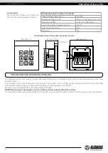
VENTILATOR CONTROL
The ventilator is operated with a control panel.
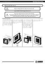
WARNING!
• The control panel must be fixed on a surface in operational position!
• Do not switch the buttons on the unsecured panel to avoid false speed switching!
• Pressing the buttons quickly and shortly may result in malfunction of the unit!
• Press the button precisely in the desired sector of the control panel to switch the speed.
The following parameters are set with the control panel:
• Ventilator speed stage: I, II, III;
• Operation mode: Regeneration or Ventilation;
• Timer-based operation of the ventilator: 4 hours at speed III or 8 hours at speed I.
The control panel displays the following parameters:
• current ventilator speed;
• current operation mode of the ventilator;
• timer operation status (on/off )
• filter replacement/cleaning need according to indications of the filter timer (factory setting 90 days)
• emergency shutdown of the ventilator in case of a motor failure.
In case of power cut-off, the set parameters are saved in the non-volatile memory of the control panel.
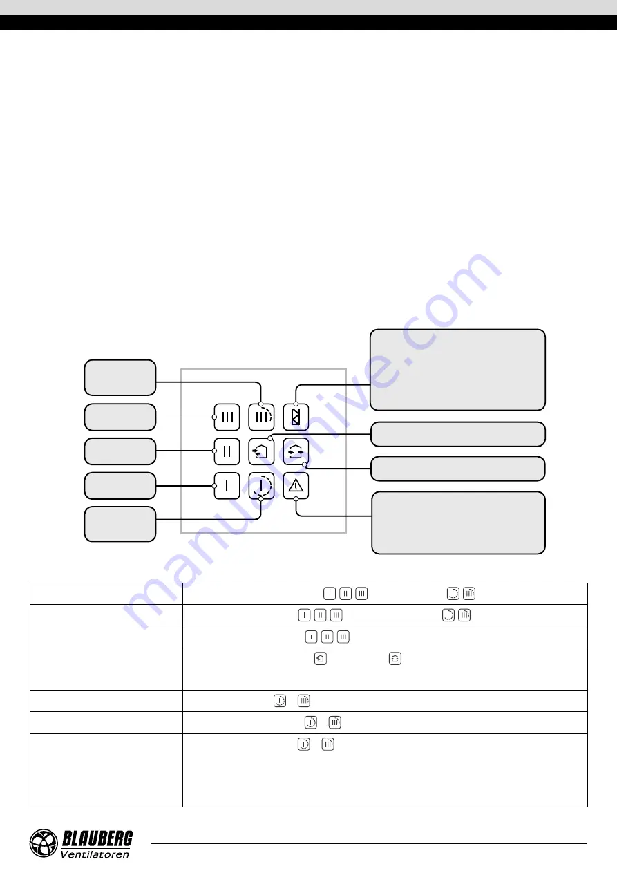
DESCRIPTION OF FUNCTIONS OF THE CONTROL PANEL BUTTONS
Timer
Speed III
4 hours
Speed III
Speed II
Speed I
Timer
Speed I
8 hours
REGENERATION
VENTILATION
The ALARM indicator glows in case of emergency stop
of the motor, as a result of which the unit stops.
Resetting alarm indication:
press and hold the ALARM indicator until the
indicators start blinking rapidly.
After expiry of the period set for the filter timer (factory
setting 90 days) the FILTER contamination indicator
starts glowing. In this case, clean or replace the filters
and reset the filter timer.
Resetting the filter timer and the filter replacement
indication: press and hold the FILTER indicator.
Turning the unit on
Press any of speed selection buttons
,
,
or the timer buttons
,
.
Turning the unit off
Press the active speed button
,
,
or the active timer button
,
, if no speed button is active.
Unit speed selection
Press the inactive speed button
,
,
.
Unit operation mode selection
Press the inactive REGENERATION
or VENTILATION
button.
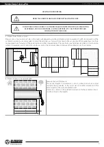
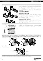
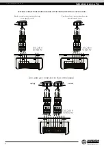
The direction of air flow in the unit (supply and extract mode ) is set when connecting the unit according to the
external connections wiring diagram.
Turning the timer on
Press the TIMER button
or
.
Timer selection
Press the inactive TIMER button
or
.
Turning the timer off
Press the active TIMER button
or
.
If the timer period expires:
• The unit continues operation at a set speed. The speed can be selected before switching on the
timer as well as during the timer-based operation.
• The unit turns off if the speed was not selected.


