background image

www.blaubergventilatoren.de

vento eco(2) a50-4 Pro

7

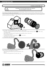
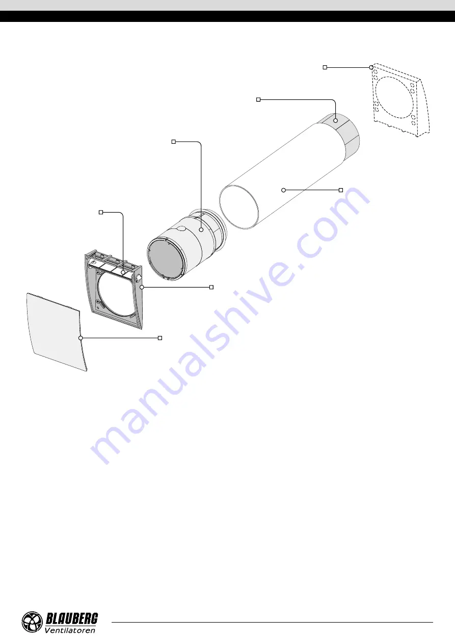
Front part of the indoor unit

Fulfils the decorative function. It is a part of the indoor unit design and directs the air flow upwards.

Back part of the indoor unit

Designed for fixing the indoor unit to the wall, contains a swivel damper for closing 
the air duct in case of prolonged downtime of the ventilator.

Cartridge

Construction consisting of a fan, a regenerator and filters.

Generates air flow, provides heat recovery and air cleaning.

Swivel damper

Air duct

Plastic air duct.

Outer ventilation hood

Prevents ingress of water and foreign objects into the ventilator. 

Each ventilator model has a matching outer hood model.

Sound absorbing material

A layer of sound-absorbing material for attenuation 

of noise generated during the ventilator operation.

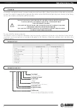
Ventilator design

VENTILATOR OPERATION MODES

The ventilator has two operation modes: 

Ventilation: 

the ventilator runs either in extract or supply mode at a set speed.

In this mode, when two ventilators are installed, one of them supplies and the other one extracts the air.

Regeneration: 

the ventilator runs in two cycles, 70 seconds each, with heat and humidity regeneration.

• 

Cycle I. 

Warm stale air is extracted from the room and flows through the ceramic regenerator, which gradually absorbs heat and 

humidity. In 70 seconds, as the ceramic regenerator gets warmed, the ventilator is switched to supply mode.

• 

Cycle II. 

Fresh intake air from outside flows through the ceramic regenerator, absorbs accumulated moisture and is heated up to 

the room temperature. In 70 seconds, as the ceramic regenerator gets cooled down, the ventilator is switched to air extract mode 
and the cycle is renewed. If two ventilators are installed, they operate with opposite rotation directions in this mode. While one 
ventilator supplies air, the other one extracts it.

Summary of Contents for Vento Eco A50-4 Pro Series

Page 1: ...Single room reversible energy recovery ventilator USER S MANUAL EN Vento Eco A50 4 Pro Vento Eco2 A50 4 Pro...
Page 2: ...he field of ventilation systems and should be able to work in accordance with workplace safety rules as well as construction norms and standards applicable in the territory of the country The informat...

Page 3: ...Protect the electric parts of the unit against ingress of water Do not allow children to operate the unit Disconnect the unit from power mains prior to any technical maintenance Do not store any expl...

Page 4: ...ted air must not contain any flammable or explosive mixtures evaporation of chemicals sticky substances fibrous materials coarse dust soot and oil particles or environments favourable for the formatio...

Page 5: ...dicated on the unit casing 160 6 5 16 Air duct length wall thickness A Outer ventilation hood Indoor unit 215 8 7 16 60 2 3 8 250 9 13 16 160 6 5 16 160 6 5 16 80 3 1 8 80 3 1 8 55 2 3 16 55 2 3 16 Ov...

Page 6: ...manually actuated air damper WARNING Air damper closing does not turn off the ventilator but only blocks the air flow The external protective grille or the ventilation hood on the outer wall prevents...

Page 7: ...sign VENTILATOR OPERATION MODES The ventilator has two operation modes Ventilation the ventilator runs either in extract or supply mode at a set speed In this mode when two ventilators are installed o...

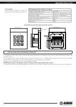
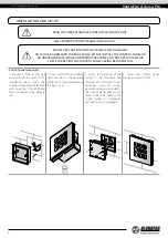
Page 8: ...mounting 1 Prepare a hole in the wall and route all the wires to the installation place Insert the supplied mounting box for flush wall mounting The mounting box is included in the delivery set 2 Use...

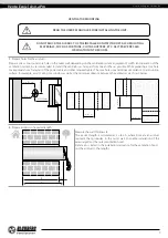
Page 9: ...nce to a mounting surface for example a wall ceiling or a window as well as the minimum distance between the ventilators are shown below min 1 m min 1 m min 1 m min 500 mm 180 mm min 500 mm min 500 mm...

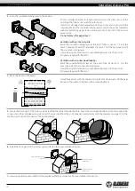
Page 10: ...ion Mark the sound absorbing layer at the end of the air duct as 1 Cut the excessive part of the sound absorbing layer Insert the adjusted and ready sound absorbing layer into the air duct No glue is...

Page 11: ...ilt into the stationary wiring The circuit breaker trip current must be selected depending on the ventilator current consumption For details please refer to the table on page 5 The actual conductor cr...

Page 12: ...ir exhaust unit Each unit is connected as an air supply unit 100 240 V 50 60 Hz P1 T1 L N P2 T2 P2 T2 BLACK RED BLUE YELLOW BLACK RED BLUE YELLOW T P 100 240 V 50 60 Hz P1 T1 P1 T1 L N P2 T2 T P BLACK...

Page 13: ...SpeedI 8hours REGENERATION VENTILATION The ALARM indicator glows in case of emergency stop of the motor as a result of which the unit stops Resetting alarm indication press and hold the ALARM indicato...

Page 14: ...open or close the air duct turn one of the handles on the side walls of the indoor unit until it stops as shown in the figure The vertical position of the handle corresponds to the position OPEN the...

Page 15: ...s as they get clogged but not less than once in three months After expiry of the period set for the hour meter factory setting 90 days the filter replacement indicator appears on the control panel dis...

Page 16: ...ts and troubleshooting Problem Possible reasons Troubleshooting The fan does not start up during the ventilator start up The control panel displays no information and does not respond to the button pr...

Page 17: ...arranty does not apply to the following cases User s failure to submit the unit with the entire delivery package as stated in the user s manual including submission with missing component parts previo...

Page 18: ...www blaubergventilatoren de Vento Eco 2 A50 4 Pro 18...

Page 19: ...of the complete unit delivery with the user s manual The warranty terms are acknowledged and accepted Customer s Signature The Vento Eco ____________ unit is installed pursuant to the requirements sta...

Page 20: ...www blaubergventilatoren de B127 2EN 01...

Reviews: