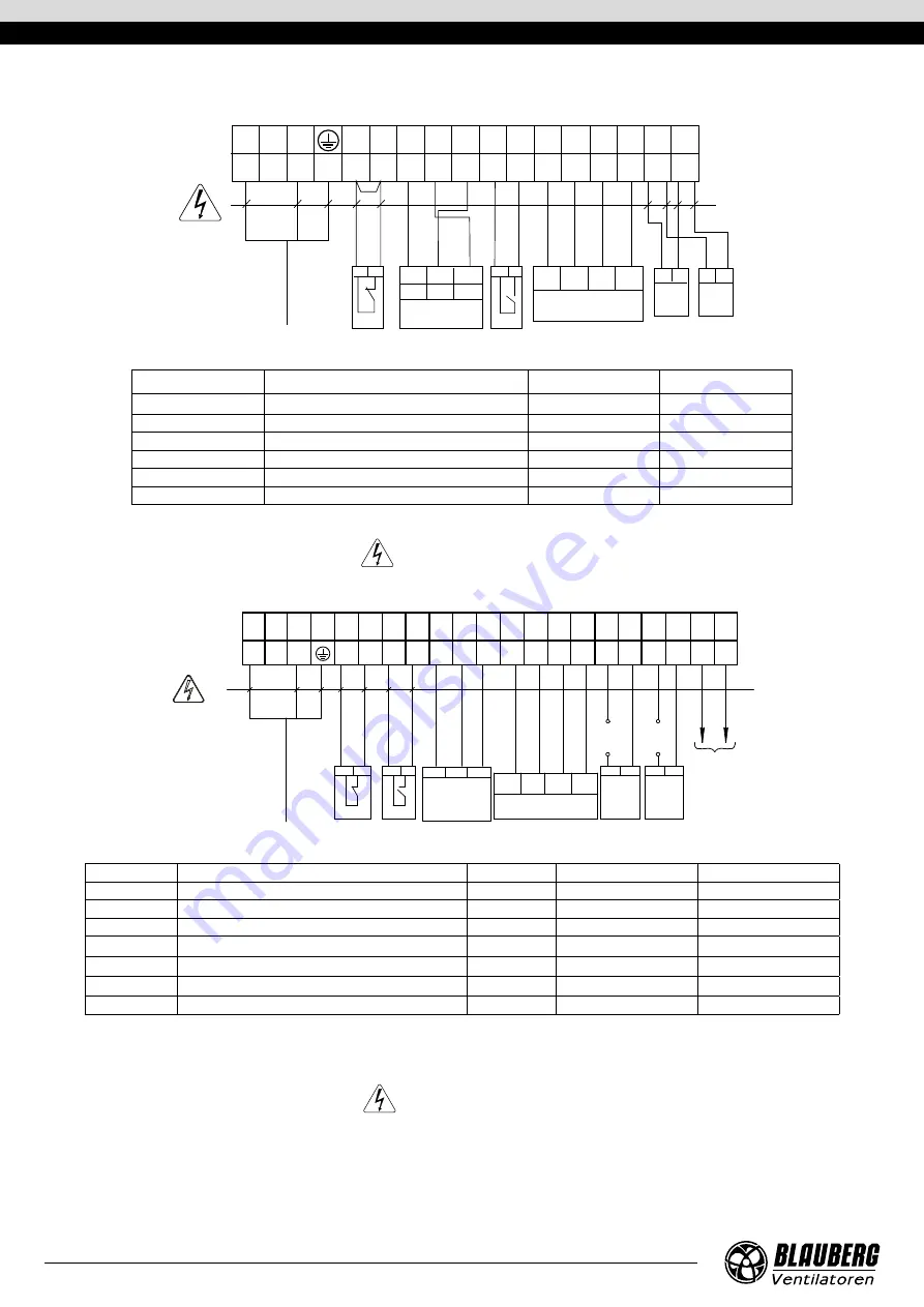
EXTERNAL WIRING DIAGRAM FOR THE KOMFORT EC S(1)(B)160/350/550(-E) S14 UNITS
2 1
3 2 1
HV1*
+U
0-10V
GND
1 2 3 4 5 6 7 8 9 10 11 12 13 14 15 16 17
L
N
C
PK PK +U
+U
+U
0-10V
SM-LSM-N
GND
GND
GND
NO
P1
SM1* SM2*
Tx
Tx
Rx
Rx
Х1
CO2*
PK1*
2 1
2 1
2 1
Power input
230 VAC
Remo
ve
the jumper
Whit
e
Whit
e
Br
own
Br
own
Gr
een
Gr
een
Yello
w
Designation
Name
Model
Wire**
SM1*
Supply air damper actuator
2 x 0.75 mm
2
SM2*
Extract air damper actuator
2 x 0.75 mm
2
РК1*
Contact from fire alarm panel
NC
2 x 0.75 mm
2
С02*
CO
2
sensor
NO
2 x 0.75 mm
2
HV2*
Humidity sensor
3 x 0.75 mm
2
P1
External control panel
4 x 0.25 mm
2
*Is not included in the delivery set.
** Maximum connecting cable length is 20 m!
— ELECTRIC SHOCK HAZARD!
EXTERNAL CONNECTIONS DIAGRAM FOR THE KOMFORT EC S(1)B160(-E) S21 UNITS
GND
GND
X1
L SQ
PE
N
NO
NO
A B
NC C
C
C NO C NO C
+24V
+24V
L 2 N 9 10 11 12 13 14 15 16 17 18 19 20 21 22 23 24 25
0-10V
GND
А
В
+24V
1
2
PK1*
1
2
1
2
P1*
1
2
1
2
1
2
C
C
U
*
Boost*
1
2
SM1*
1
2
SM2*
U**
U**
CO2*
GND
0-10V +24V
Brown
Yello
w
Gr
een
W
hit
e
Power input
230 VAC
Designation
Name
Model
Wire***
Note
SM1*
Supply air damper actuator
NO
2 x 0.75 mm
2
3A, 30DC/~250 AC
SM2*
Extract air damper actuator
NO
2 x 0.75 mm
2
3A, 30DC/~250 AC
РК1*
Contact from fire alarm panel
NC
2 x 0.75 mm
2
CCU*
CCU control
NO
2 x 0.75 mm
2
3A, 30DC/~250 AC
P1*
External control panel
4 x 0.25 mm
2
Boost*
On/Off contacts for the Boost mode
NO
2 x 0.75 mm
2
CO2
External CO
2
sensor
NO
3 x 0.75 mm
2
*Is not included in the delivery set.
** The U supply voltage of the SM1, SM2 external dampers is selected depending on the type of dampers.
*** Maximum connecting cable length is 20 m!
Output parameters: terminals 19-24 - 3A, 30VDC / ~ 250 VAC (“dry contact”).
— ELECTRIC SHOCK HAZARD!
www.blaubergventilatoren.de
KOMFOrt EC S(1)(B)160/350/550(-E)
12


