www.blaubergventilatoren.de
11
Axis / Tubo
INSTALLATION AND CONNECTION TO POWER MAINS
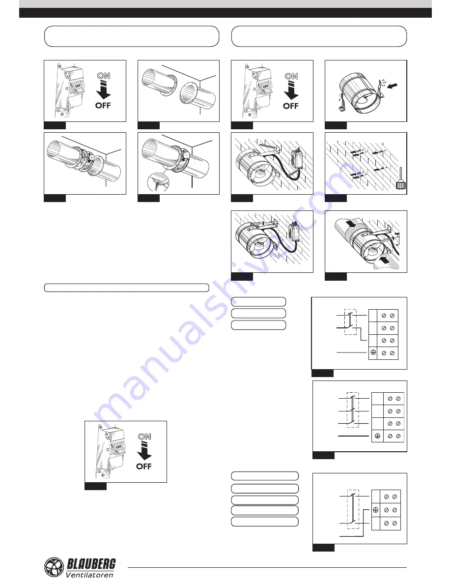
MOUNTING SEQUENCE
AXIS-F
Fig.
28
Fig.
29
Fig.
30
Fig.
31
MOUNTING SEQUENCE
TUBO-M / TUBO-MZ
Fig.
32
Fig. 3
3
Fig. 3
4
Fig. 35
L
N
X1
1
2
3
N
L
QF
PE
~230 V
50 Hz
4
L2
L1
QF
PE
~400 V
50 Hz
L2
L1
X1
2
4
1
3
L3
L3
AXIS-Q
AXIS-QR
AXIS-F
Connection of the fan to power mains is allowed by a qualified electrician
only. The rated electrical parameter are stated on the rating plate.
No modifications of internal connections are allowed and will result in void
warranty. Connect the fan only to power mains with valid electric standards.
The house cabling system must be equipped with an automatic switch at
the external input. Connect the fan to power mains through the automatic
switch.
The contact gap on all poles at least 3 mm. The automatic switch trip current
must be in compliance with the fan current consumption, refer Table on pag-
es
5–6. Install the automatic switch to ensure prompt access.
Cut power supply to the fan off by turning the automatic electric switch QF
to OFF position (fig. 38). Take steps to prevent activation of the automatic
switch.
Fig. 3
8
The fan wiring diagram is shown in fig. 39–41.
Connection sequence of the fan, shown on fig. 42–56.
AXIS-QA
AXIS-QRA
TUBO-M / TUBO-MZ
L
N
X1
1
2
3
N
L
QF
PE
~230 V
50 Hz
Fig 3
9
Fig. 40
L
N
X1
1
2
3
N
L
QF
PE
~230 V
50 Hz
4
L2
L1
QF
PE
~400 V
50 Hz
L2
L1
X1
2
4
1
3
L3
L3
Fig. 41
Single-phase fans
Three-phase fans
Fig. 3
6
Fig. 37
AXIS-QA G
TUBO-F


