background image

blaubergventilatoren.de

CiViC eC dB 1000

2

CONTENTS

SAFETY REQUIREMENTS

•  Please read the user’s manual carefully prior to installing and operating the unit.
•  All user’s manual requirements as well as the provisions of all the applicable local and national 

construction, electrical, and technical norms and standards must be observed when installing 
and operating the unit.

•  The warnings contained in the user’s manual must be considered most seriously since they 

contain vital personal safety information.

•  Failure to follow the rules and safety precautions noted in this user’s manual may result in an 

injury or unit damage.

•  After a careful reading of the manual, keep it for the entire service life of the unit.
•  While transferring the unit control, the user’s manual must be turned over to the receiving 

operator.

This user’s manual is a main operating document intended for technical, maintenance, and operating staff.
The manual contains information about purpose, technical details, operating principle, design, and installation of the CIVIC EC DB 1000 
unit  and all its modifications.
Technical and maintenance staff must have theoretical and practical training in the field of ventilation systems and should be able to 
work in accordance with workplace safety rules as well as construction norms and standards applicable in the territory of the country.
The information in this user’s manual is correct at the time of the document’s preparation.
The Company reserves the right to modify the technical characteristics, design, or configuration of its products at any time in order to 
incorporate the latest technological developments.
No part of this publication may be reproduced, stored in a retrieval system, or transmitted, in any form or by any means in any information 
search system or translated into any language in any form without the prior written permission of the Company.

Safety requirements ..................................................................................................................................................................... 2
Purpose ................................................................................................................................................................................................ 5
Delivery set ........................................................................................................................................................................................ 5
Designation key .............................................................................................................................................................................. 5
Technical data .................................................................................................................................................................................. 6
Design and operating principle  .......................................................................................................................................... 7
Mounting and set-up .................................................................................................................................................................. 10
Connection to power mains .................................................................................................................................................. 17
Control ................................................................................................................................................................................................. 18
Technical maintenance .............................................................................................................................................................. 18
Troubleshooting ............................................................................................................................................................................. 21
Storage and transportation regulations .......................................................................................................................... 21
Manufacturer’s warranty ........................................................................................................................................................... 22
Certificate of acceptance .......................................................................................................................................................... 23
Seller information .......................................................................................................................................................................... 23
Installation certificate .................................................................................................................................................................. 23
Warranty card ................................................................................................................................................................................... 23

Summary of Contents for CIVIC EC DB 1000

Page 1: ...Single room air handling unit USER S MANUAL EN CIVIC EC DB 1000 CIVIC EC DBE 1000 CIVIC EC DBE2 1000 ...

Page 2: ...VIC EC DB 1000 unit and all its modifications Technical and maintenance staff must have theoretical and practical training in the field of ventilation systems and should be able to work in accordance with workplace safety rules as well as construction norms and standards applicable in the territory of the country The information in this user s manual is correct at the time of the document s prepar...

Page 3: ...onnecting the unit to power mains Do not operate the unit outside the temperature range stated in the user s manual Do not operate the unit in aggressive or explosive environments Do not touch the unit controls with wet hands Do not carry out the installation and maintenance operations with wet hands Do not wash the unit with water Protect the electric parts of the unit against ingress of water Do...

Page 4: ...ring operation Do not direct the air flow produced by the unit towards open flame or ignition sources Do not block the air duct when the unit is switched on In case of continuous operation of the unit periodically check the security of mounting Do not sit on the unit and avoid placing foreign objects on it Use the unit only for its intended purpose THE PRODUCT MUST BE DISPOSED SEPARATELY AT THE EN...

Page 5: ...rgy efficient premises The unit is a component part and is not designed for stand alone operation It is rated for continuous operation Transported air must not contain any flammable or explosive mixtures evaporation of chemicals sticky substances fibrous materials coarse dust soot and oil particles or environments favourable for the formation of hazardous substances toxic substances dust pathogeni...

Page 6: ... 267 271 275 Heat recovery efficiency 83 93 Heat exchanger type counter flow SEC class A A A OVERALL AND CONNECTING DIMENSIONS mm 2327 601 2xØ312 1026 567 23 5 416 399 219 5 11 5 400 237 416 416 416 416 1764 194 1164 421 237 1242 50 7xØ11 194 R5 5 11 76 Ø8 TECHNICAL DATA The unit is designed for application with the ambient temperature ranging from 1 C to 40 C and relative humidity up to 80 In ord...

Page 7: ... danger appears if the exhaust air temperature downstream of the heat exchanger is below 5 C and the intake air temperature upstream of the heat exchanger is below 3 C After increase of the exhaust air temperature the unit reverts to the previous operation mode The difference between the supply and extract air flow temperature leads to condensate generation Condensate is collected in the drain pan...

Page 8: ...blaubergventilatoren de CIVIC EC DB 1000 8 1 15 14 13 12 11 18 10 8 15 16 17 17 17 17 6 7 2 4 3 5 9 17 17 ...

Page 9: ...ract air damper actuator 5 Bypass damper actuator 6 Extract fan 7 Supply fan 8 Heat exchanger 9 Supply air preheater 10 Supply air reheater 11 Supply filter differential pressure switch 12 Extract filter differential pressure switch 13 Control unit 14 Wi Fi antenna 15 Mounting brackets 16 Mounting frame 17 Decorative panels 18 Drain pan Air movement inside the unit ...

Page 10: ...he supplied mounting bracket and L brackets To get the best performance of the unit and to minimize turbulence induced air pressure losses connect the straight air duct section to both unit spigots Minimum straight air duct length equal to 1 air duct diameter on intake side equal to 3 air duct diameters on outlet side To protect the internal parts of the unit from ingress of foreign objects it is ...

Page 11: ...ts on the room side From the outside of the room the air duct must be cut flush with the wall of the building for the installation of ventilation grilles purchased separately Adjustment of the air duct length is possible before and after its fixation in the wall In the first case the required length must be calculated before mounting and in the second case sufficient access must be provided to cut...

Page 12: ...move the preheater in the CIVIC EC DBE 1000 and CIVIC EC DBE2 1000 units a Unscrew the screws on the cover of the heater control unit and remove it Remove the screws that secure the heater b Remove the heater with the control box Hang and fasten the unit to the ceiling and wall Install three units fixed to each other on the mounting bracket and connect the air ducts to the unit spigots On the left...

Page 13: ...e left block Install and tighten the mounting screws supplied to securely connect the middle block to the left and right ones Install the casing back Mount and connect the front block Mount the front block in the reverse order in the CIVIC EC DBE 1000 and CIVIC EC DBE2 1000 units reinstall the heater Connect the connectors of the control devices according to the marking ...

Page 14: ...rgventilatoren de CIVIC EC DB 1000 14 Install the decorative panels Install the decorative panels according to the marking using the screws and close the fastening holes with plugs 10 6 2 1 9 5 4 11 3 12 8 7 ...

Page 15: ...B 1000 15 Install the hinged doors Remove the retaining screws before hanging the hinged doors Hang the doors Install the retaining screws to prevent the doors from sliding off Attach the safety cables to the doors with the safety hooks ...

Page 16: ...rainage for the condensed water otherwise it is accumulated inside the unit that may cause the equipment damage and condensate outflow to the room The condensate drainage system is designed for normal operation in premises with air temperatures above 0 C If the expected ambient air temperatures are below 0 C the condensate drainage system must be equipped with heat insulation and pre heating facil...

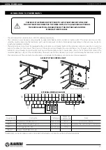
Page 17: ...eaker is the next current in the standard trip current row following the maximum current of the connected unit The automatic circuit breaker is not included in the delivery set and can be ordered separately ACCESS TO THE CONTROL UNIT EXTERNAL WIRING DIAGRAM L1 L1 N N L2 L2 L3 L3 PE X1 X3 400 V C 4 C 2 NO 3 NC 1 24V 8 A 6 B 7 GND 5 24V A B GND 10 9 1 2 Boost P1 1 2 PK1 CCU Designation Unit name Cab...

Page 18: ...aning of the unit and the following operations 1 Filter maintenance Dirty filters increase air resistance in the system and reduce supply air volume The filters require cleaning not less than 3 4 times per year Vacuum cleaning is allowed After two consecutive cleanings filters must be replaced For new filters contact the Seller Filter removal 1 Disconnect the unit from power mains 2 Open the left ...

Page 19: ...he unit Heat exchanger removal 1 Disconnect the unit from power mains 2 Open the middle hinged door of the unit with the key 3 Loosen the screws securing the protective plates Then move the plates so that the screw caps match the holes and remove the plates 4 Unscrew the screws holding the drain pan and remove it 5 Unscrew the beam screws and remove it 6 Unscrew the screws on the shorter retaining...

Page 20: ...logged with leaves and other objects reducing the unit performance and supply air delivery Check the supply grille twice per year and clean it as required 5 Ductwork system maintenance once in 5 years Even regular fulfilling of all the maintenance operations prescribed above may not completely prevent dirt accumulation in the air ducts which leads to air pollution and reduces the unit capacity Duc...

Page 21: ...t exchanger is clogged Clean the heat exchanger Noise vibration The impeller s is clogged Clean the impeller s The fan or casing screw connection is loose Tighten the screw connection of the fans or the casing against stop No anti vibration connectors on air duct pipe flanges Install anti vibration connectors STORAGE AND TRANSPORTATION REGULATIONS Store the unit in the manufacturer s original pack...

Page 22: ... the Seller for warranty service The manufacturer s warranty does not apply to the following cases User s failure to submit the unit with the entire delivery package as stated in the user s manual including submission with missing component parts previously dismounted by the user Mismatch of the unit model and the brand name with the information stated on the unit packaging and in the user s manua...

Page 23: ...ION CERTIFICATE The CIVIC EC DB_______________ unit is installed pursuant to the requirements stated in the present user s manual Installation Stamp Company name Address Phone Number Installation Technician s Full Name Installation Date Signature The unit has been installed in accordance with the provisions of all the applicable local and national construction electrical and technical codes and st...

Page 24: ...blaubergventilatoren de B177 1EN 01 ...

Reviews: