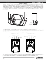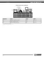
External control units wiring diagram:
2
3
4
14
13
12
11
10
9
8
7
6
5
15
L
1
External device
NO (CO2 sensor)
PK fire alarm panel
(remove the jumper
while connecting the contact)
120/60 Hz
Control
panel
- Tx Rx +
GND Tx
Rx +U
3
2
1
GND
+U
0-10V
GND
+U 0-10V
NО
N
PE
PК
РК
C
X1
16
SM-L
17
SM-N
Humidity
sensor
W
hit
e
Bro
wn
Gr
een
Yello
w
XP
QF
Electric actuators
of the external air dampers
SM1
supply
L1 N
SM2
exhaust
L1 N
Designation
Name
Model
Wire**
N.o
External control device contacts
LF230
2 x 20 AWG
SМ1*
Supply air damper actuator
LF230
2 x 20 AWG
SМ2 *
Extract air damper actuator
LF230
2 x 20 AWG
РК*
Contact from fire alarm panel
NO
2 x 20 AWG
* Is not included in the delivery set.
** Maximum connecting cable length is 20 m!
www.blauberg.us
Komfort EC S5B270(-E) S14
12


