background image

SAFETY REQUIREMENTS

CONTENTS

Safety requirements ..................................................................................................................................................................... 2
Purpose ................................................................................................................................................................................................ 4
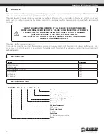
Delivery set ........................................................................................................................................................................................ 4
Designation key .............................................................................................................................................................................. 4
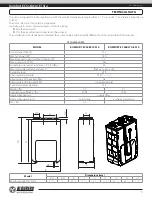
Technical data .................................................................................................................................................................................. 4
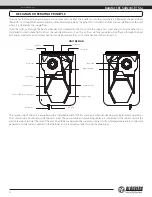
Unit design and operating principle ................................................................................................................................. 6
Installation and set-up................................................................................................................................................................ 8
Connection to power mains .................................................................................................................................................. 10
Unit control ....................................................................................................................................................................................... 11
Technical maintenance .............................................................................................................................................................. 12
Storage and transportation regulations .......................................................................................................................... 13
Manufacturer’s warranty ........................................................................................................................................................... 14
Certificate of acceptance .......................................................................................................................................................... 15
Seller information .......................................................................................................................................................................... 15
Installation certificate .................................................................................................................................................................. 15
Warranty card ................................................................................................................................................................................... 15

This user’s manual is a main operating document intended for technical, maintenance, and operating staff.
The manual contains information about purpose, technical details, operating principle, design, and installation of the 
Komfort EC S5B270(-E) S14 unit and all its modifications.
Technical and maintenance staff must have theoretical and practical training in the field of ventilation systems and should be able to 
work in accordance with workplace safety rules as well as construction norms and standards applicable in the territory of the country.
The information in this user’s manual is correct at the time of the document’s preparation.  
The Company reserves the right to modify the technical characteristics, design, or configuration of its products at any time in order to 
incorporate the latest technological developments.
No part of this publication may be reproduced, stored in a retrieval system, or transmitted, in any form or by any means in any information 
search system or translated into any language in any form without the prior written permission of the Company.

•  Please read the user’s manual carefully prior to installing and operating the unit.
•  All user’s manual requirements as well as the provisions of all the applicable local and national construction, electrical, and technical 

norms and standards must be observed when installing and operating the unit.

•  The warnings contained in the user’s manual must be considered most seriously since they contain vital personal safety information.
•  Failure to follow the rules and safety precautions noted in this user’s manual may result in an injury or unit damage.
•  After a careful reading of the manual, keep it for the entire service life of the unit.
•  While transferring the unit control, the user’s manual must be turned over to the receiving operator.

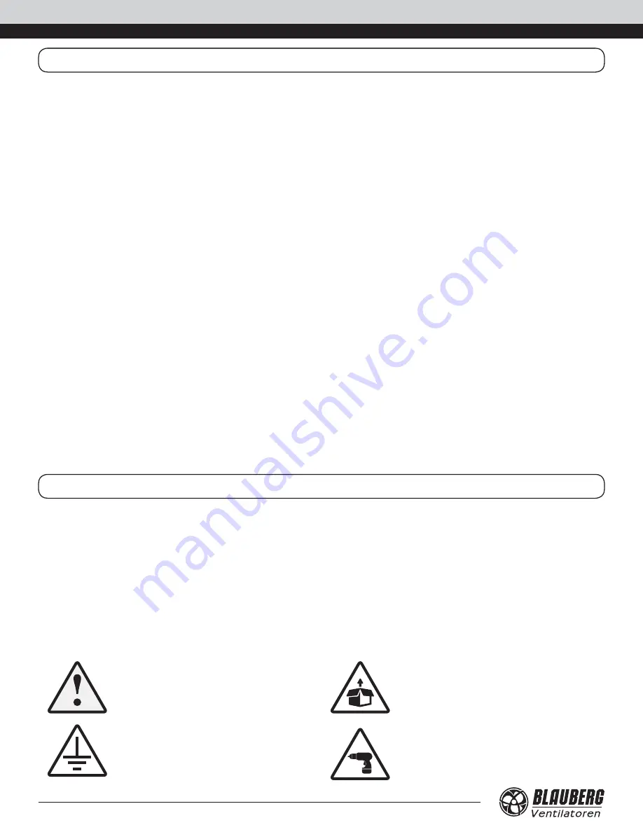
UNIT INSTALLATION AND OPERATION SAFETY PRECAUTIONS

•  Disconnect the unit from power mains prior 

to any installation operations.

•  Unpack the unit with care.

•  The unit must be grounded!

•  While installing the unit, follow the safety 

regulations specific to the use of electric 
tools.

www.blauberg.us

Komfort EC S5B270(-E) S14

2

Summary of Contents for Komfort EC S5B270 S14

Page 1: ...Air handling unit USER S MANUAL EN Komfort EC S5B270 S14 Komfort EC S5B270 E S14 ...

Page 2: ...ny time in order to incorporate the latest technological developments No part of this publication may be reproduced stored in a retrieval system or transmitted in any form or by any means in any information search system or translated into any language in any form without the prior written permission of the Company Please read the user s manual carefully prior to installing and operating the unit ...

Page 3: ...t ingress of water Do not allow children to operate the unit Disconnect the unit from power mains prior to any technical maintenance Do not store any explosive or highly flammable substances in close proximity to the unit When the unit generates unusual sounds odour or emits smoke disconnect it from power supply and contact the Seller Do not open the unit during operation Do not direct the air flo...

Page 4: ...favourable for the formation of hazardous substances toxic substances dust pathogenic germs NAME NUMBER Air handling unit 1 pc User s manual 1 pc Control panel user s manual 1 pc Control panel 1 pc Installation kit 1 pc Packing box 1 pc THE UNIT SHOULD NOT BE OPERATED BY CHILDREN OR PERSONS WITH REDUCED PHYSICAL MENTAL OR SENSORY CAPACITIES OR THOSE WITHOUT THE APPROPRIATE TRAINING THE UNIT MUST B...

Page 5: ...ounter flow Heat exchanger material polystyrene enthalpy membrane SEC class А А ØD L H H2 B L1 H1 L2 ØD1 Model Dimensions mm Ø D Ø D1 B L L1 L2 H H1 H2 Komfort EC S5B270 E S14 4 15 16 9 16 23 1 4 12 7 16 4 5 8 11 5 16 33 9 16 35 3 16 1 5 8 The unit is designed for indoor application with the ambient temperature ranging from 1 C up to 40 C and relative humidity up to 80 The unit is rated as a Class...

Page 6: ...very minimizes heat losses which reduces the cost of space heating in the cold season UNIT DESIGN Supply fan Bypass damper Extract fan Supply air filter Drain pan Control unit Drain pipe Counter flow heat exchanger Extract air filter Supply air filter Intake air Supply air Extract air Exhaust air The service side of the unit is equipped with a detachable plate for filter and heat exchanger cleanin...

Page 7: ...heatexchangerfreezeprotectionfunctionoftheunitisimplemented with a temperature sensor installed in the exhaust air duct downstream of the heat exchanger In case of a freezing danger the supply fan is turned off and the heat exchanger is warmed up with warm extract air flow The recommended sensor or thermostat operating temperature is 37 F exhaust air temperature If necessary this setting can be ch...

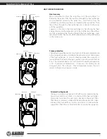
Page 8: ...ct the straight air duct section to the spigots while installing Minimum straight air duct length equal to 1 air duct diameter on the intake side equal to 3 air duct diameters on outlet side If the air ducts are too short or not connected protect the unit parts from ingress of foreign objects To prevent uncontrollable access to the fans the spigots may be covered with a protecting grille or other ...

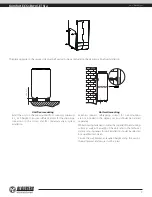
Page 9: ... system installation Unit wall mounting Fasteners dowels self tapping screws for wall mounting are not included in the delivery set and should be ordered separately Whilechoosingfastenersconsiderthematerialofthemounting surface as well as the weigh of the unit refer to the Technical data section Fasteners for unit installation should be selected by a qualified technician Secure the wall bracket at...

Page 10: ... U trap kit purchased separately The pipe slope downwards must be at least 3 min 3 Drain hose U trap Sewage system Drain pipe The condensate drainage system is designed for normal operation in premises with air temperatures above 32 F If the expected ambient air temperatures are below 32 F the condensate drainage system must be equipped with heat insulation and pre heating facilities SERVICE SIDE ...

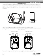
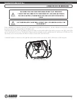
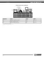
Page 11: ... must ensure free access for quick power off of the unit The trip current must be in compliance with the consumption current refer to Technical data Complete the electrical connections through the terminal block in the control unit as shown in the external wiring diagram Access to the control unit DISCONNECT THE UNIT FROM POWER MAINS PRIOR TO ANY OPERATIONS THE UNIT MUST BE CONNECTED TO POWER MAIN...

Page 12: ...SM N Humidity sensor White Brown Green Yellow XP QF Electric actuators of the external air dampers SM1 supply L1 N SM2 exhaust L1 N Designation Name Model Wire N o External control device contacts LF230 2 x 20 AWG SМ1 Supply air damper actuator LF230 2 x 20 AWG SМ2 Extract air damper actuator LF230 2 x 20 AWG РК Contact from fire alarm panel NO 2 x 20 AWG Is not included in the delivery set Maximu...

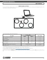
Page 13: ...00 High speed 100 100 0 100 Unit speed with the closed dry contact of the external control unit 100 100 0 100 Filter cleaning replacement interval h 2160 3 months 0 10000 Humidity level 60 30 80 The list of the adjustable parameters can be expanded in new versions of the software Setting troubleshooting and upgrading of the software version is made by the service technician To download the softwar...

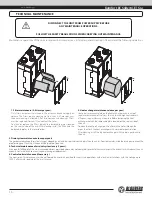
Page 14: ...ean the heat exchanger pull it out drain the water through the pipes then flush the heat exchanger with warm detergent solution After cleaning install the dry heat exchanger with the drain pan back to the unit 3 Drain system maintenance once per year The condensate drainage drain line may get clogged by dirt and dust particles contained in the exhaust air Pour some water inside the drain pan to ch...

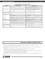
Page 15: ...he screw connection of the fans or the casing all the way No anti vibration connectors on air duct pipe flanges Install anti vibration connectors Water leakage only for the Komfort EC S5B270 E units The drainage system is soiled damaged or installed incorrectly Clean the drain line if necessary Check the drain line slope angle Make sure that the U trap is filled with water and the drain pipes are ...

Page 16: ...er than by BLAUBERG faulty installation or negligence accident improper maintenance or repair other than by BLAUBERG faulty installation or installation contrary to recommended installation instructions Labor to remove and replace products is not covered The duration of any implied warranty is limited to the time period specified for the express warranty Some states do not allow limitations on how...

Page 17: ...www blauberg us Komfort EC S5B270 E S14 17 ...

Page 18: ...www blauberg us Komfort EC S5B270 E S14 18 ...

Page 19: ..._ S14 unit has been connected to power mains pursuant to the requirements stated in the present user s manual Installation Company Stamp Seller Address Phone Number Installation Technician s Full Name Installation Date Signature The unit has been installed in accordance with the provisions of all the applicable local and national construction electrical and technical codes and standards The unit o...

Page 20: ...www blauberg us BUSA170 1EN 01 ...

Reviews: