


10
www.blaubergventilatoren.de
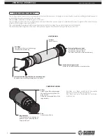
VENTO Eco / VENTO Eco2
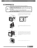
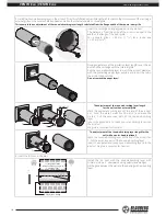
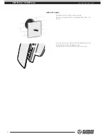
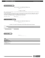
3. Install the sound-absorbing layer in the air duct. Prior to installation adjust its length with respect to the dimensions of the cartridge,
external grille or the outer ventilation hood as well as the internal square or round grille.
This example shows adjustment of the sound-absorbing layer length calculated from the flange width of the square inner grille.
Insert the cartridge during adjustment in the air duct.
The distance L from the edge of the air duct is equal to the
width of the flange of the inner grille.
For a square grille L = 40 mm (1
9
/
16
") for a round one
L = 20 mm (
13
/
16
")
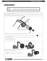
During adjustment of the insulation layer length cover the air
duct and the cartridge with the internal grille.
Roll the sound-absorbing layer to match the air duct diameter
with the protecting paper layer outside and insert the roll in
the air duct against stop.
Do not remove the paper layer!
1
2
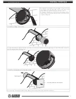
50 mm (2”)
1
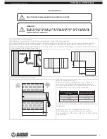
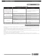
The adjustment of the sound-absorbing layer length
for the unit with an external grille
Mark the sound-absorbing layer at the end of the air duct
as 1. From the mark 1 measure 50 mm (2’’) and make the
mark 2. Cut the excessive part of the sound-absorbing
layer.
Insert the adjusted and ready sound-absorbing layer into
the air duct.
No glue is required for fixation!
1
The adjustment of the sound-absorbing layer length for the
unit with an outer hood (optional)
Mark the sound-absorbing layer at the end of the air duct as
1. Cut the excessive part of the sound-absorbing layer.
Insert the adjusted and ready sound-absorbing layer into the
air duct. No glue is required for fixation!
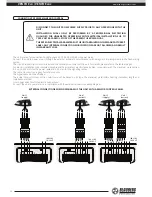
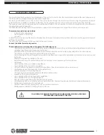
4. Insert the air duct in the wall.
Fill the gaps between
the wall and the opening with
a mounting foam.
Polystyrene wedge
min 3
°
C
Install the air duct with the sound-absorbing layer with
minimum slope 3˚ downwards using polystyrene wedges.
Fill the gaps between the wall and the opening with a mounting
foam.


