background image

www.blaubergventilatoren.de

13

VENTO Eco / VENTO Eco2

UNIT CONTROL

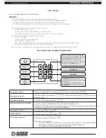
The unit is operated with the control panel.

WARNING!

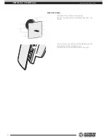
The control panel must be fixed on a surface in operational position!

Do not press the buttons on the unsecured panel to avoid false speed switching!

Pressing the buttons quickly and shortly may result in malfunction of the unit!

Press the button precisely in the desired sector of the control panel to switch the speed.

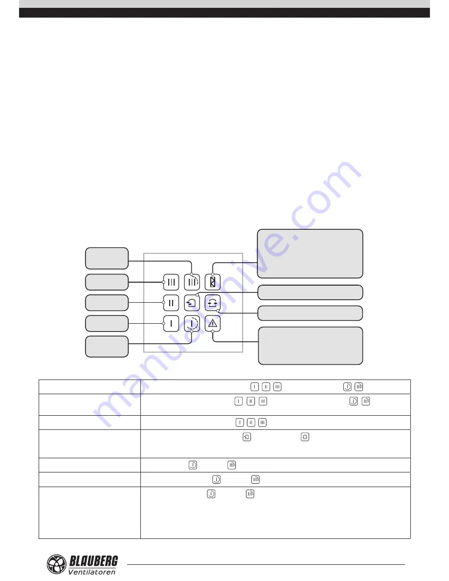
The following parameters are set with the control panel: 

•  unit operation speed: I, II, III;

•  unit operation mode: REGENERATION or VENTILATION;

•  timer-based operation of the unit: 4 hours at speed III or 8 hours at speed I. 

The control panel displays the following parameters:

•  current unit speed

•  current operation mode of the unit

•  timer operation status (on/off)

•  filter replacement/cleaning need according to indications of the filter timer (factory setting 90 days)

•  emergency shutdown of the unit in case of a motor failure 

In case of power cut-off the set parameters are saved in the non-volatile memory of the control panel.

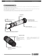
UNIT CONTROL WITH A SENSOR CONTROL PANEL

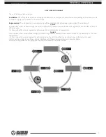
Timer

Speed 

III

4 hours

Speed 

III

Speed 

II

Speed 

I

Timer

Speed I

8 hours

REGENERATION

VENTILATION

After expiry of the period set for the filter timer 

(factory setting 90 days) the 

FILTER 

contamination 

indicator starts glowing. In this case clean or 

replace the filters and reset the filter timer.

Resetting the filter timer and the operating hours: 

press and hold the 

FILTER 

indicator.


The 

ALARM 

indicator glows in case of 

emergency stop of the motor, as a result of which 

the unit stops.
Resetting alarm indication: press and hold 

the 

ALARM 

indicator until the indicators start 

blinking rapidly.


Turning the unit on

Press any of speed selection buttons  ,  ,   or the timer buttons  ,  .

Turning the unit off

Press the active speed button  , 

 or the active timer button  , 

, if no speed 

button is active.

Unit speed selection

Press the inactive speed button  ,  ,  .

Unit operation mode selection

Press the inactive REGENERATION   or VENTILATION   button.

The direction of air flow in the unit (supply and extract mode) is set when connecting the unit 

according to the external connections wiring diagram.

Turning the timer on

Press the timer   button or  .

Timer selection

Press the inactive timer   button or  .

Turning the timer off

Press the active timer   button or  .

If the timer period expires: 

•  The unit continues operation at a set speed. The speed can be selected before 

switching on the timer as well as during the timer-based operation.

•  The unit turns off if the speed was not selected.

Summary of Contents for VENTO Eco

Page 1: ...OPERATION MANUAL EN VENTO Eco VENTO Eco2 SINGLE ROOM ENERGY RECOVERY VENTILATION UNIT ...

Page 2: ... DO NOT The user s manual consisting of the technical details operating instructions and technical specification applies to the installation and mounting of the single room energy recovery reversible ventilator Vento Eco hereinafter referred to as the unit Safety requirements 2 Purpose 4 Delivery set 4 Technical data 5 Unit design and operating logic 6 Mounting and set up 8 Connection to power mai...

Page 3: ...e the unit Disconnect the unit from power mains prior to any technical maintenance Do not store any explosive or highly flammable substances in close proximity to the unit When the unit generates unusual sounds odour or emits smoke disconnect it from power supply and contact the Seller Do not open the unit during operation Do not direct the air flow produced by the unit towards open flame or ignit...

Page 4: ... hazardous substances toxic substances dust pathogenic germs Name Number VENTO Eco A50 S1 Pro VENTO Eco2 A50 S1 Pro Air duct 1 item 2 items Sound absorbing layer 1 item 2 items Assembled cartridge 1 item 2 items Internal round ventilation grille 1 item 2 items Internal square ventilation grille 1 item 2 items External grille 1 item 2 items Control panel 1 item 1 item Fastening set 1 pack 1 pack Mo...

Page 5: ... 0 3 20 0 5 23 0 6 13 0 3 20 0 5 23 0 6 Noise level attenuation dB A Sones 41 2 5 Heat recovery efficiency 92 86 78 92 86 78 Ingress protection IP24 The air duct length and the internal grille model depend on the unit model For details please refer to the Designation Key The external grille may be replaced with an outer ventilation hood Overall dimensions of the ventilation hood are stated in the ...

Page 6: ... of supply air flow The unit consists of a protecting internal grille with a decorative panel a cartridge an air duct with a sound absorbing material layer and a protecting external ventilation grille or a hood The cartridge is the basic functioning part of the unit The cartridge consists of a fan a regenerator and two filters that ensure rough air filtration and prevent ingress of dust and foreign...

Page 7: ...turizes the regenerator and transfers up to 97 of heat energy In 70 seconds as the ceramic regenerator gets warmed the unit is switched to supply mode Cycle II Fresh intake air from outside flows through the ceramic regenerator absorbs accumulated moisture and is heated up to the room temperature In 70 seconds as the ceramic regenerator gets cooled down the unit is switched to air extract mode and...

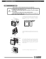
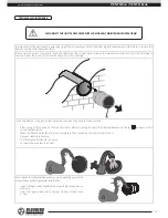
Page 8: ... a hole in the wall and route all the wires to the installation place Insert the supplied mounting box for flush wall mounting The mounting box is included in delivery 94 mm 3 11 16 34 mm 1 5 16 3 mm 1 8 2 Use a screwdriver to carefully undo the clips on the backside of the control panel and remove the back cover 3 Screw the backside of the casing to the mounting box through the fastening holes Fa...

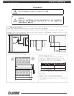
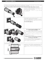
Page 9: ...le a wall ceiling or a window as well as the minimum distance between the units are shown below min 1 m min 39 3 8 min 1 m min 39 3 8 min 1 m min 39 3 8 min 500 mm min 1 m Ø 180 mm Ø 7 1 16 min 500 mm min 19 11 16 min 500 mm min 19 11 16 2 Prepare air ducts of required length A B L Measure the wall thickness B The air duct length is calculated as L B A where A means an air duct segment that protru...

Page 10: ... the roll in the air duct against stop Do not remove the paper layer 1 2 50 mm 2 1 The adjustment of the sound absorbing layer length for the unit with an external grille Mark the sound absorbing layer at the end of the air duct as 1 From the mark 1 measure 50 mm 2 and make the mark 2 Cut the excessive part of the sound absorbing layer Insert the adjusted and ready sound absorbing layer into the a...

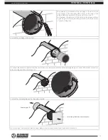
Page 11: ...age to the cable insulating material cut off the excess of the mounting foam 5 Install the cartridge in the air duct 6 Connect the socket connector from the control panel in compliance with the external wiring diagram Connect the socket connectors of the cartridge and the control panel 7 Install the internal grille and fix the external grille External grille Internal grille with a decorative panel...

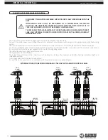
Page 12: ...o the table at page 5 For electric installations use insulated durable and heat resistant electric leads cables conductors with the minimum cross section 0 5 up to 0 75 mm2 for the power cable and 0 25 mm2 for the signalling cables The cable cross section is given for reference only The signal cable must be shielded The actual conductor cross section selection must be based on its type the maximum...

Page 13: ...EGENERATION VENTILATION After expiry of the period set for the filter timer factory setting 90 days the FILTER contamination indicator starts glowing In this case clean or replace the filters and reset the filter timer Resetting the filter timer and the operating hours press and hold the FILTER indicator The ALARM indicator glows in case of emergency stop of the motor as a result of which the unit...

Page 14: ...LOSING Disconnect the unit from power supply Remove the grille with the decorative panel from the air duct Open Close To close the air duct pull a small handle between the grille shutters to the left against stop To open the air duct pull this handle to the right ...

Page 15: ...an the filters as they get contaminated but not less than once in three months After expiry of the period set for the filter timer factory setting 90 days the filter replacement indicator appears on the control panel display Wash the filters and let those dry out completely Then install the dry filters in the air duct Vacuum cleaning is allowed The filter rated service life is 3 years For new filt...

Page 16: ...gged Clean or replace the filter Clean the fan and the heat exchanger Noise vibration The impeller is clogged Clean the impeller Store the unit in the manufacturer s original packing box in a dry ventilated premise at ambient temperatures from 5 C 41 F up to 40 C 104 F Storage environment must not contain aggressive vapours and chemical mixtures provoking corrosion insulation and sealing deformati...

Page 17: ...nual including submission with missing component parts previously dismounted by the user Mismatch of the unit model and the brand name with the information stated on the unit packing and in the user s manual User s failure to ensure timely technical maintenance of the unit External damage to the unit casing excluding external modifications as required for installation and internal components cause...

Page 18: ...ive 93 68 EEC on the approximation of the laws of the Member States relating to electromagnetic compatibility which relate to electrical appliances used in set voltage classes This certificate is issued following test carried out on samples of the product referred to above Quality Inspector s Stamp Manufacture Date ____________________ Company Expert s Full Name Date Signature Heat recovery single...

Page 19: ...___________________________________ _______________________________________________________________________________________ _______________________________________________________________________________________ _______________________________________________________________________________________ _______________________________________________________________________________________ ____________...

Page 20: ...VENTO_Eco_v 2 1 _EN ...

Reviews: