background image

GROUND

+12V

REM

CH 6 

CH 5 

CH 4 

CH 3 

CH 2 

CH 1 

POWER

PROTECT

GAIN

HIGH PASS

LOW PASS

5V

0.2V

10Hz

 4KHz

0dB

 12dB

30Hz

 250Hz

BASS EQ

X-OVER

HIGH

GAIN

5V

0.2V

10Hz

 4KHz

CH 5/CH 6

CH 3/CH 4

HIGH PASS

CH MOD E

CH 4 CH 6

CH 2

CH 1 

LINE INPUT

CH 2 

CH 3 

CH 4 

CH 5 

CH 6 

REMOTE

CH 1/CH 2

LOW /BP

FULL

GAIN

5V

0.2V

10Hz

 4KHz

HIGH PASS

SPECIFICATION

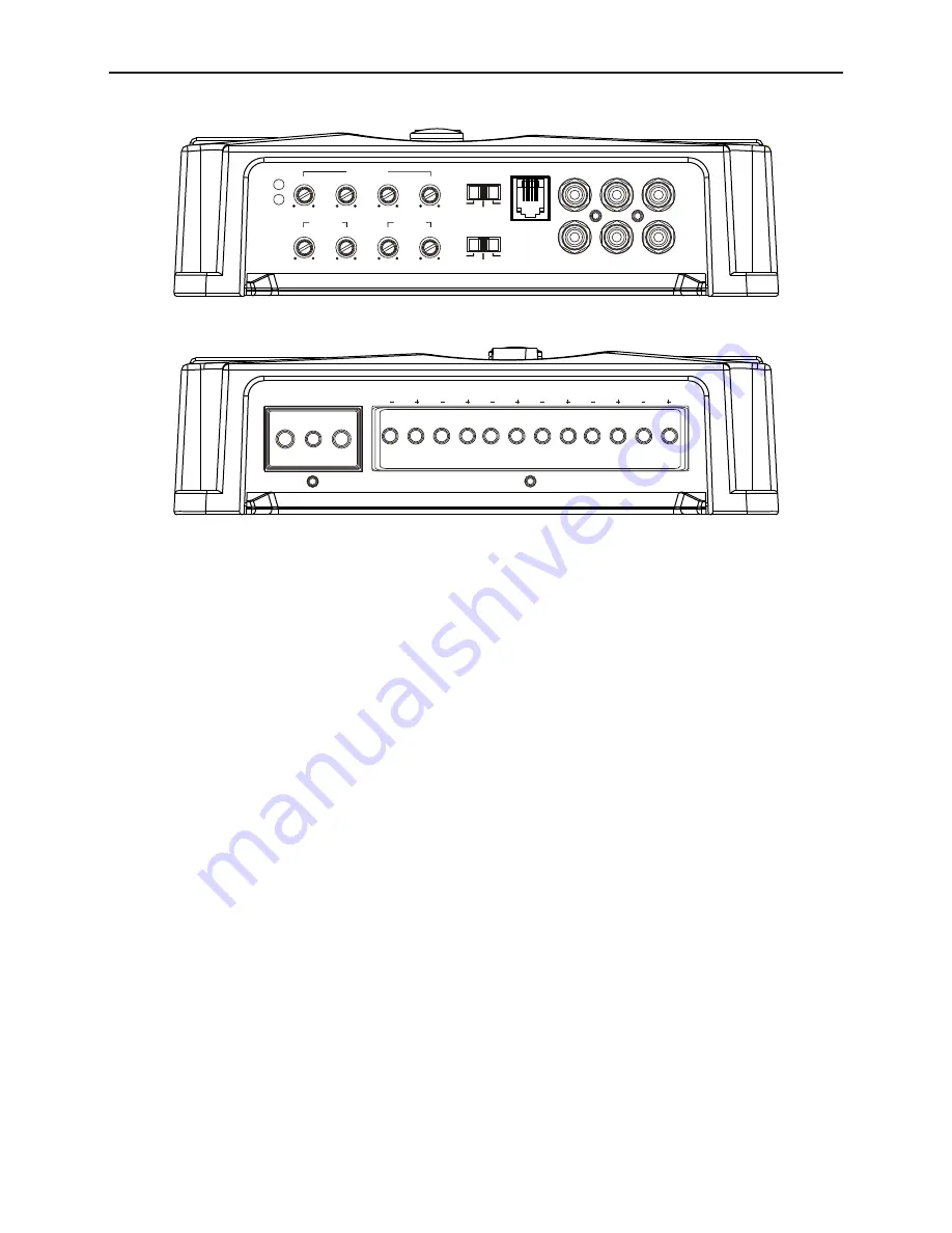
MPA 680 FUNCTION CONTROLLING & WIRING DIAGRAM

4

Power


Amplifier


Voltage Supply 


14.4V

Idling Current  


1.5A

Fuse 


40A x 2

Consumption @ 2Ω, 14.4 VDC 

50A

(Max Musical Power) 

Amplifier Class 


CLASS D

Channel 

  6

Layer 

PCB 

  Double 

Max Output Power @ 4 ohms 

110W x 6

RMS Power 4 ohms 


80W x 6

RMS Power 2 ohms 


135W x 6

RMS Power 4 ohms Bridge 

300 x 2

Signal-To-Noise Ratio 


95dB

Frequency Range 


5-35kHz

Gain 

Adjust 

  0.5-5V

Bass Boost Frequency   

45Hz

Bass Boost Level 


12dB

Total Harmonic Distortion 

0.06%

Crossover Frequency 


30-250Hz (L), 10Hz-4kHz (H)

Dimension (W x H x D)   

337 x 192 x 52mm

Net 

Weight 

  3.1kg

Summary of Contents for MPA 11500

Page 1: ...VELOCITY POWER MPA 480 MPA 680 MPA 11500 Operating and Installation Instruction Enjoy it ...

Page 2: ... to 12V and GND terminals Connect the 12V power input lead only when the rest of the connections has been properly set In no event shall Blaupunkt be liable for any direct indirect punitive incidental special consequential damages to property or life improper storage whatsoever arising out of or connected with the use or misuse of our products USA CANADA Product not intended for sale in the United...

Page 3: ...CH 2CH CH MODE Power Amplifier Voltage Supply 14 4V Idling Current 1 1A Fuse 30A x 2 Consumption 2Ω 14 4 VDC 40A Max Musical Power Amplifier Class CLASS D Channel 4 PCB Layer Double Max Output Power 4 ohms 120W x 4 RMS Power 4 ohms 90W x 4 RMS Power 2 ohms 150W x 4 RMS Power 4 ohms Bridge 300 x 2 Signal To Noise Ratio 95dB Frequency Range 5 35kHz Gain Adjust 0 5 5V Bass Boost Frequency 45Hz Bass B...

Page 4: ...M FUSE GROUND 12V REM CH 1 CH 2 CH 3 CH 4 Battery 2 4 ohms FUSE GROUND 12V REM CH 1 CH 2 CH 3 CH 4 4 ohms Speaker Connection Speaker Subwoofer Bridged Connection FUSE Battery FUSE 2 4 ohms 2 4 ohms 2 4 ohms 2 4 ohms 2 4 ohms ...

Page 5: ...NTROLLING WIRING DIAGRAM 4 Power Amplifier Voltage Supply 14 4V Idling Current 1 5A Fuse 40A x 2 Consumption 2Ω 14 4 VDC 50A Max Musical Power Amplifier Class CLASS D Channel 6 Layer PCB Double Max Output Power 4 ohms 110W x 6 RMS Power 4 ohms 80W x 6 RMS Power 2 ohms 135W x 6 RMS Power 4 ohms Bridge 300 x 2 Signal To Noise Ratio 95dB Frequency Range 5 35kHz Gain Adjust 0 5 5V Bass Boost Frequency...

Page 6: ...dged Connection MPA 680 WIRING DIAGRAM GROUND 12V REM CH 6 CH 5 CH 4 CH 3 CH 2 CH 1 Battery FUSE 2 4 ohms 2 4 ohms 2 4 ohms 2 4 ohms 2 4 ohms 2 4 ohms GROUND 12V REM CH 6 CH 5 CH 4 CH 3 CH 2 CH 1 Battery FUSE 2 4 ohms 2 4 ohms 2 4 ohms 2 4 ohms ...

Page 7: ... 4V Idling Current 1 4A Fuse 40A x 4 Consumption 2Ω 14 4 VDC 70A Max Musical Power Amplifier Class CLASS D Channel 1 Layer PCB Double Max Output Power 4 ohms 900W x 1 RMS Power 4 ohms 640W x 1 RMS Power 2 ohms 1000W x 1 RMS Power 1 ohms 1500Wx 1 Signal To Noise Ratio 104dB Frequency Range 10 250Hz Gain Adjust 0 2 5V Bass Boost Frequency 45Hz Bass Boost Level 12dB Total Harmonice Distortion 0 03 Cr...

Page 8: ...7 FUSE GROUND SUBWOOFER 12V REM Speaker Connection MPA 11500 WIRING DIAGRAM Battery FUSE ...

Page 9: ...TPUT 16AWG Using a dual amplifier configuration the main unit amplifier has total control over the sub unit amplifier When using dual amplifier to operate subwoofer the positive terminal of the subwoofer voice coil must be connected to the positive terminal of the main unit amplifier and the negative terminal of the subwoofer voice coil must be connected to the positive terminal of the sub unit am...

Page 10: ...KHz 0dB 12dB 30Hz 150Hz BASS EQ CH 3 CH 4 CH 1 CH 2 HIGH PASS LOW PASS X OVER FULL LOW BP CH 1 LINE INPUT CH 2 CH 3 CH 4 4CH 2CH CH MODE FUSE GROUND SUBWOOFER 12V REM MPA AMPLIFIER STANDARD WIRING DIAGRAM RCA OUTPUT REMOTE TURN ON FUSE KEEP GND WIRE SHORT OR LESS THAN 18 12V WIRE 5 7ft USE 10AWG 7 15ft USE AWG OVER 15ft USE 4AWG ...

Page 11: ...rossover Control setting Observe if the device is still producing noise after turning on and off the amplifier If yes examine if the cables are correctly connected and if the cables and radio are in good condition Repair or replace if the cables or the radio are not in good condition Ensure RCA connections are properly connected Ensure input level of the device matches the signal level of the head...

Page 12: ...1 121 18 009 02 01 1 121 18 010 02 01 1 121 18 011 02 01 Designed and engineered by Blaupunkt Competence Center ...

Reviews: