2. Device Introduction
The Alarm System supports multiple devices which are listed in this section. For accessory
devices, please refer to individual device manual for detail instruction
3
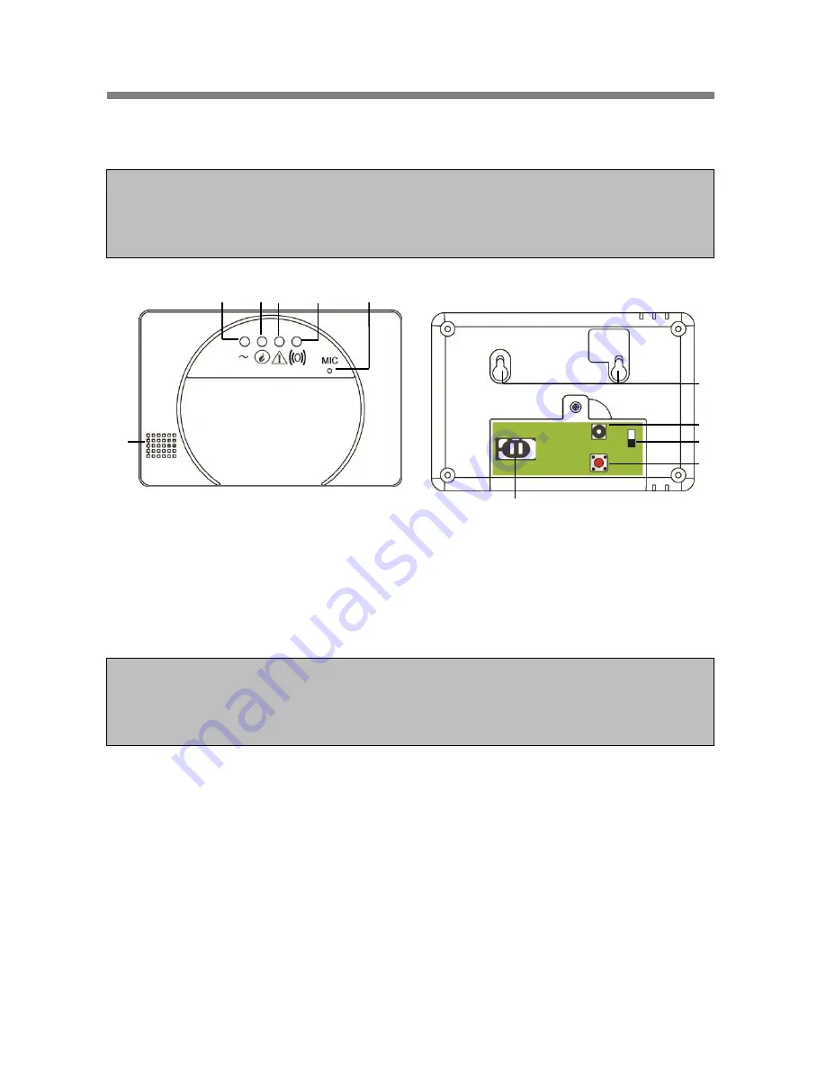
Control Panel
A 9V 1A adaptor is supplied to power the Control Panel. Please wait until a SIM card is inserted
before connecting the adaptor.
In addition to the adaptor, there is a rechargeable battery inside the Control Panel that serves
as back up power in case of power failure. Once you have connected the AC power supply,
please turn on the battery switch to charge the battery. It takes about 72 hours to fully charge
the battery. When fully charged, the battery can serve as a back-up power source for about 18
hours.
The Control Panel requires a
SIM card
to send reports and receive commands. Before you
insert the SIM card into GSM module, please note the following:
1. The SIM card must be able to make and receive both telephone calls and SMS messages
normally. Data only SIM cards are
NOT compatible
with the Control Panel.
2. Please make sure SIM card
PIN code is disabled
. To check whether SIM Card PIN code is
disabled, insert the SIM card into a working mobile phone, go to SIM card PIN code setting
in mobile phone setting functions to disable the SIM card PIN code.
3. If a
prepaid SIM card
is used, please check the SIM card information carefully as each SIM
card provider has their own policy: Some SIM cards have a validity period and must be
extended before they expires; some SIM cards will expire automatically if they are not used
for a certain time period. When using prepaid SIM card, please make sure you fully
understand its user policy, and check the SIM card’s remaining value regularly with your
service provider to make sure the SIM card is functioning normally.
NOTE:
The basic package you purchase includes the following devices:
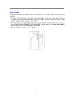
1 x PIR Sensor, 1 x Door Contact, 1 Remote Controller
Other useful devices are available separately, see www.blaupunkt.com.
IMPORTANT NOTE:
The Battery Switch is set to
OFF
by factory default. Please make sure the switch is turned
ON
after connecting the AC power to the Control Panel, otherwise the battery will not be charged
and the Control Panel will be without back up power when power fails.
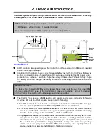
Buzzer
Mounting
Holes
DC Jack
Battery
Switch
Function
Button
GSM Module
Power
LED
Mode
LED
Fault
LED
GSM
LED
Microphone
Summary of Contents for SA 2500
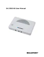
Page 1: ...SA 2500 Kit User Manual ...

