OM-AF20.1 E V1.02
May 15, 2015
Page 31
AF20
.1
CATALYST MONITORING cont.
4.
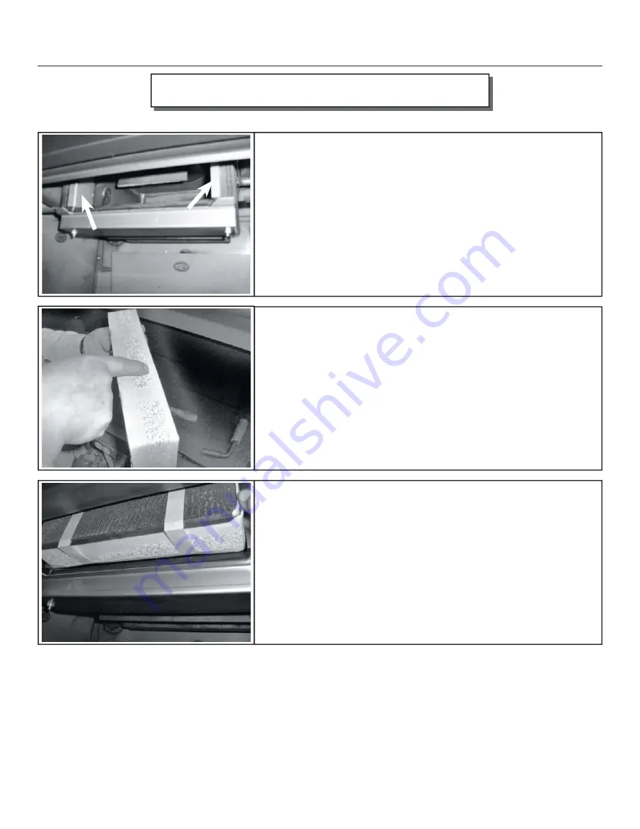
Now that the combustor has been removed you’ll be able to see
one stainless bypass retainer on each side. Th
ese can remain in place
and do not need to be removed. Th
ese clips are not fi xed in position and
can fall into the fi rebox. Make sure they are in position before replacing
the combustor. Using the same screwdriver or pocket knife, scrape any
old gasket from the surface areas of the dome. Th
e dome is the housing
that surrounds the combustor. If you clean your existing combustor,
you’ll need to order replacement combustor gasket. It is always a good
idea to have a spare combustor gasket on hand prior to performing any
maintenance. If you purchase a new combustor a new gasket will already
be applied to the combustor.
5.
Th
is new combustor already has the gasket installed. Note the 1” wide
masking tape. Th
is tape will help to keep the leading edge of the gasket
from snagging during installation. If you’ve cleaned your combustor,
wrap the combustor gasket as you see here and use the 1” masking tape
around the perimeter front and rear. During the fi rst fi re the masking
tape will burn off and the combustor gasket will swell providing a tight
seal. It is this tight seal that improves effi
ciency and performance. You
should never burn your stove without a combustor gasket installed.
6.
Since the combustor is only 2” deep, there is ample room to lift the
new combustor into place.
REMEMBER TO HAVE THE TAB
ACROSS THE BOTTOM EDGE OF THE COMBUSTOR AS
IT IS INSTALLED
. Slowly push the combustor in at the top apply
even pressure to the left and right corners. Th
is will allow for a better
view of the bottom edge for the fi nal fi tting.
DO NOT FORCE THE
COMBUSTOR INTO THE DOME. TAKE YOUR TIME AND
WORK IT INTO PLACE SLOWLY.


