OM-BRII90I E V1.05 wo768
August 25, 2015
Page 19
BRII/90I
OPTIONAL ASSEMBLY INSTRUCTIONS
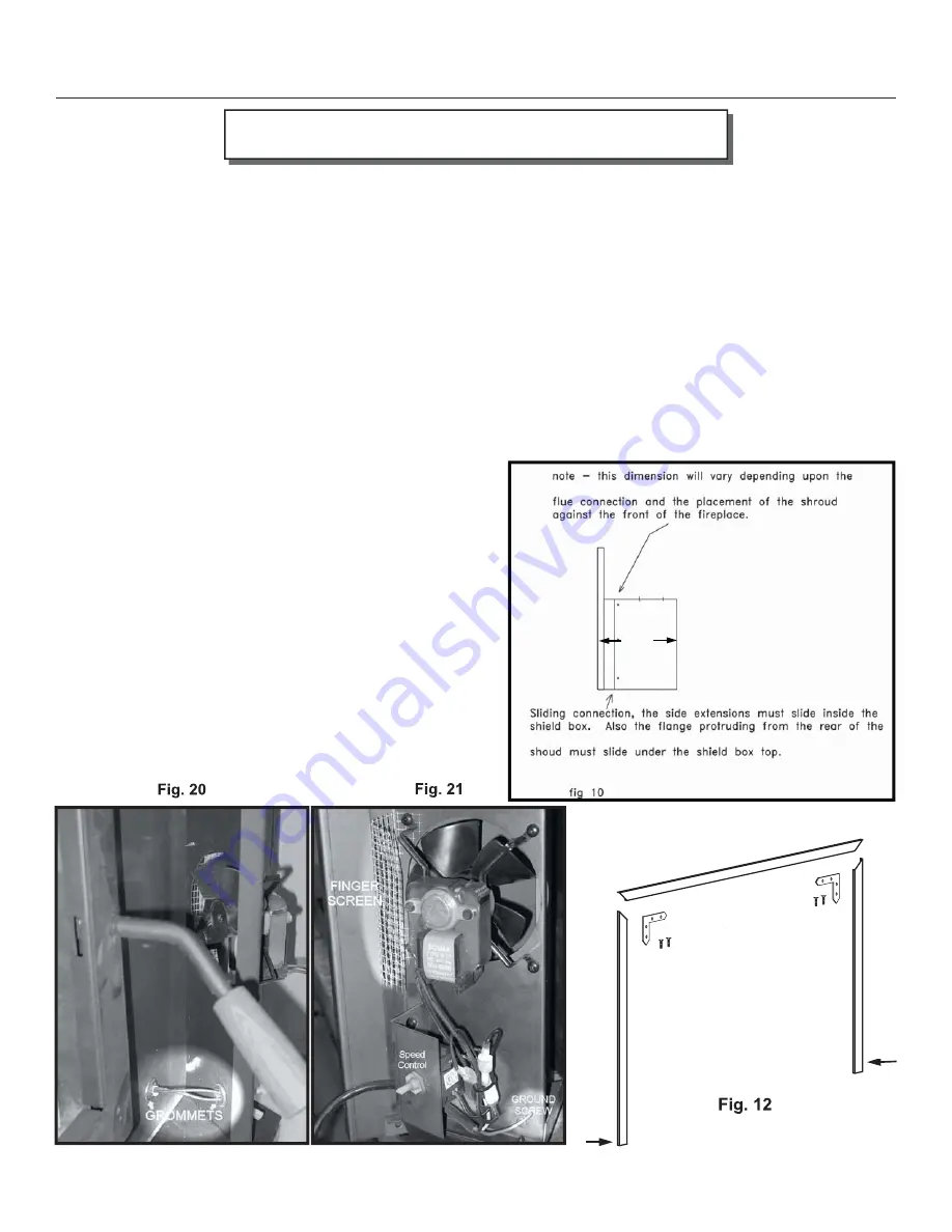
Assemble the trim strips as shown in (
Fig. 12
) and attach to the shroud outer edge using the screws provided. Return to
step 5 and continue the installation.
Optional Fans Installation:
(Note: Th
e following instructions pertain to both fans on the left and right sides of the stove.)
1. Determine which side of the stove the power cord for the fan should be located.
2. Install a grommet in the 5/8” hole on each side of the shroud. Install a grommet in the bottom 5/8” hole of the fan
housing piece (
Fig. 20
) which will contain the rheostat.
3. Slide the wires, which are attached to the shield box, through the grommets on the shroud. Note: It may be easier to
slide the wire with the larger male connector through fi rst.
4. Install Bomax fan (with printing on fan right side up) and fi nger screen (
Fig. 21
). Th
e fan attaches from the front, to
the fan housing, with the fi nger screen attaching under the outside with 2 fan mounting screws. Th
e screen will need
to be bent to act as a fi nger protector (
Fig. 21
).
5. Mount the rheostat, with 2 screws (
Fig. 21
). Connect the green ground wire by using the green screw and star washer
provided. Be sure to place the star washer between the round
lug and the frame of the housing. Insert a wire, from the
rheostat, with a male connector and a wire with a female
connector through the grommet in the fan housing. Connect
these 2 wires to the male and female connectors on the shield
box wiring harness. Connect the remaining male and female
connectors to the fan. Connect shield box wiring harness, on
other side of unit, to fan on other side using same method.
6. Proceed to step 13 on previous page.
7. See the electrical diagram (
Fig. 11
) for electrical connection.
Note: the fans are connected in parallel.
17”
INSTALLATION INSTRUCTIONS cont.
Left
L-Brac kets X2
Top
Right
Brass Scre ws X4
Screw
Screw


