Hybrid™ Manifold
© Blichmann Engineering, LLC 2019
3
STEP ONE:
The first step to assembling your Hybrid
™
Manifold is to attach the
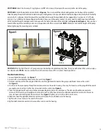
(4) leveling feet to the base of the manifold. Screw each of the feet into the holes
on the bottom of the manifold. See
Figure 1.
Once each of the leveling feet has been
set to the desired height, it can be locked in place by tightening the locking nut.
STEP TWO:
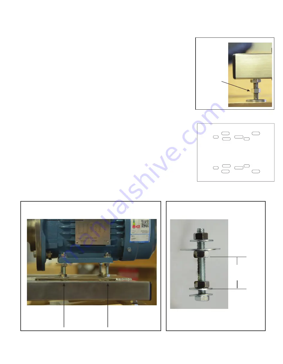
Installing the pump. If your pump comes installed, skip to Step Three.
To install your pump, determine the correct hole configuration. Align your pump mounting
holes to the base of the manifold. See
Figure 2
for mounting hole configurations.
Once you’ve selected the hole configuration that aligns with your pump, attach the pump using
the (4) 5/16” x 2½” bolts, (12) 5/16” nuts, (12) 5/16” washers and (4) 5/16” x 1.5” OD fender washers
provided. To install, remove the pump from the base. Place a washer on each bolt and insert the
assembled bolts through the bottom of your selected hole configuration. See
Figure 2.
Place
another washer and nut onto each bolt and thread all of the way down to the base. This should
hold the bolt in place.
NOTE:
We do not recommend tightening all of the way as you still need to
adjust the bolt forwards or backwards in the slot. Please see
Figure 4
to see the correct configura-
tion of how to assemble the washers, bolts and nuts.
Place another nut and washer (5/16” x 1.5” OD) on each of the 4 bolts and thread about half way
down. These nuts will be used to set the height of the pump. Place the pump on the bolts and
then place another washer and nut to hold the pump in place.
NOTE:
Do not tighten the last nut,
as you will need to adjust the height once the top of the manifold and fittings are attached to the
pump. For questions on how to assemble the proper configuration of nuts and washers, please
reference
Figure 3 and Figure 4
.
ASSEMBLY
Figure 1
Locking Nut
Please check your box to make sure you have received all parts.
Figure 3
Figure 4
Correct Configuration
A
A
B
B
A
A
B
B
A- 1 HP Pump
B- 1/5 HP Weg Pump
Figure 2
C
C
C
C
1 ½”


