15
Connecting the Controller To Your System:
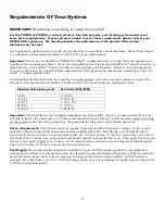
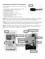
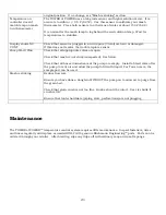
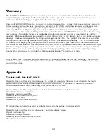
Fig 29a, and 29b show the front and rear of the controller. Connect
as directed below.
1 – Solenoid power out (switched on/off) 2A max, 120V 60hz
2 – Communications cable (cable sold separately)
3 – RTD Temperature sensor
4 – 120V 60 Hz power cable
5 – Ground cable – connect to burner frame
6 – Ignition cable connector
7 – Main power switch with integral thermal breaker
8 – Selector switch (Auto/Reset/On)
9 – Temperature controller
10 – Process label (both MASH and HLT are included)
Caution
:
Connecting a solenoid valve other than the Blichmann Engineering supplied valve can be done, but
DO NOT exceed 2A (inrush). Power out is 120V. Exceeding this power will cause permanent damage to the
ignition system and is not covered under warranty! Never exceed 30 PSI on the solenoid valve!
Warning:
The ignition system uses high voltage to create a spark! Do not power up the controller and leave
the selector switch in Reset mode until connections of the ground and ignition wires are made or shock could
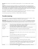
occur! ALWAYS place the black vinyl cover over the end of the ignition wire when not in use (Fig 28).
Caution:
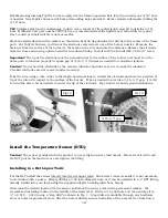
Use common sense when routing wires so that they are away from heat sources which may lead to
burned, melted, or shorted wires. Properly secure them during use with the included twist ties (search
McMaster for “reusable cable ties” for additional ties and options).
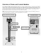
Solenoid Power Out
Ignition wire
Com port
Sensor
Cable storage
Temp Adjust
Selector switch
Ground wire
Fig. 28
Fig. 29a
Fig. 29b
Power/breaker


