background image


20

Important:

 this software is only available for Windows platform.  It is not available for Mac or portable 

devices. 


Features:

 The auto ramp/soak feature will allow you to automatically follow a user-programmed mash 

profile.  Up to 8 individual mash profiles can be stored in the controller (up to 4 rests each) and they can also 

be linked together for very complex mash profiles. In addition, the user can save an unlimited number of 
mash profile files on your computer and recall those as needed. System parameters, such as units, calibration 

offset, resetting to factory defaults etc. can easily be made through the software.  Lastly, the user can graph 
the controller output and export to a CSV file for documenting the brew day. 
 

For a preview of the software, and for instructions on operation, view our online tutorial video at the page 
listed below.  A written manual is not available for advanced operation mode. 
 

www.blichmannengineering.com/TOWER_of_POWER/TOWER_of_POWER.html   


Trouble-shooting 
 

This section provides suggestions for trouble-shooting problems that may arise with the equipment.  Please 
see our FAQ tab on the TOWER of POWER page for additional updated suggestions. 


IMPORTANT:

 Please use this guide for the fastest resolution of your problem.  Your retailer is your point of 

contact for product questions, and your fastest way to resolve your issues if the chart below does not resolve 

your problem.  Your retailer will contact Blichmann Engineering if they are unable to resolve your issues. 


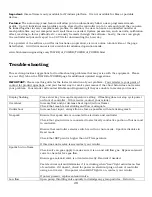
Display flashing 
 

Press enter key to accept temperature setting.  If flashing does not stop cycle power 
on front of controller.  If this recurs, contact your retailer. 

Overshoot 
 

Increase flow and/or decrease heat input (reduce flame). 
Check that mash is not sticking and flow is adequate 

Undershoot 


Increase heat input, always flow as fast as possible without sticking mash 

No spark 
 

Ensure that spark wire is connected to electrode and controller 
 
Check that ground wire is connected to electrically conductive portion of burner and 

to controller.   
 

Ensure that controller selector switch is in On or Auto mode.  Spark is disables in 
Reset mode 
 

Check that SET point is higher than ACT temperature. 
 
If this does not resolve issue contact your retailer. 

Sparks but no flame 


Check valve on gas supply to make sure it is on and will flow gas.  Bypass solenoid 
valve to check for free gas flow.  
 

Ensure gas solenoid valve is oriented correctly. Reorient if needed.   
 

Feel electrical coil and determine if it is clicking when “heat” light activates on face 
of controller. If it doesn’t, check for power on electrical plug on back of controller 
using a volt meter.  If no power when HEAT light is on, contact your retailer.   

 
If power present, replace solenoid valve. 

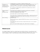
Low flow 

Open pump throttling valve quickly to dislodge any grain particles.  Return to 

Summary of Contents for TOWER of POWER

Page 1: ...ead and understood these instructions Caution Sections labeled Caution can lead to equipment damage or unsatisfactory performance of the equipment Please read these sections thoroughly If you have any questions contact your retailer or Blichmann Engineering www BlichmannEngineering com before use Important Sections labeled Important are critical to the proper performance and life of the product Se...

Page 2: ...ey can purchase the Tower module that provides all the needed plumbing and provides a convenient stand for the control module s If you already own a March 809 815 pump you can purchase the Tower without the pump Note the hoses that connect from the Tower to the pots are not included If you are a TopTiertm owner an optional mounting kit is available to mount it permanently to the stand Controller M...

Page 3: ... Flow GPM LPM 5 19 0 5 2 8 10 38 0 75 3 8 15 57 1 25 4 75 20 76 1 5 5 7 32 121 2 25 8 5 Important Grain bed flow rates are highly dependent on crush quality Move to a coarser crush if you are not able to flow at the above rates It is also recommended that you allow a 10 min dough in prior to turning on the pump to allow the air to purge from the grain and for the grain to fully absorb the water Bu...

Page 4: ...itions above with your system that is OK but it must be expected that stability and control will be compromised Note A slight overshoot of the recirculation temperature is normal and will NOT harm your enzymes Enzymes are denatured over a period of time not instantaneously We have tuned this system to offer the best match of ramp speed and stability The chart below shows a typical response curve f...

Page 5: ...out sticking your mash Note that rice hulls can aid in increasing recirculation rates Assembly The TOWER of POWERtm Modular Brewing Control ships partially assembled to allow it to be shipped more economically via ground carriers and to protect it from shipping damage Parts List The following items are shipped with the product Please check to verify that you received all the parts Contact your RET...

Page 6: ...mp March 815 if ordered with Tower Optional Dual Controller Mounting Plate reqd for mounting two controllers onto the tower 1 Plate model aCon_plate_TOP 4 10 24 X 3 8 long pan head screws Assembling the Tower Prepare a work area with a soft pad to protect the tower enclosure from getting scratched during assembly WARNING Make sure that the tower is NOT plugged in until you have fully completed the...

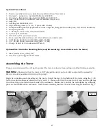
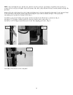
Page 7: ...ump head to so that the inlet faces down and the outlet faces up flow arrow faces up Simply remove the 4 mounting screws rotate the head and reinstall the pump head Consult the March manual if needed To wire the pump insert the pump lead wire through the rubber grommet in the back of the enclosure and feed it out the bottom of the enclosure Fig 6 Fig 3 Fig 4 Fig 5 Fig 6 Drip Shield Fig 7 Fig 8 Pla...

Page 8: ...s that are labeled pump power and connect them to the matching color leads on the pump lead using the wire nuts as shown in Fig 8 Then push the remaining wire up into the bottom of the tower Install the pump hose between the pump and the bottom of the flow meter as shown in Fig 9 Install the 90 degree QuickConnector onto the bottom of the pump Fig 10 Install the 3 8 90 degree QuickConnector onto t...

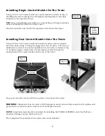
Page 9: ...wn in Fig 13 using the outer most 4 screw holes Then use an additional 4 screws to mount the assembly onto the tower as shown in Fig 12 using the inner 4 screw holes and placing the screws through the mating holes in the angle brackets on the top of the Tower Plug each controller into the GFCI receptacle on the back of the tower WARNING Make sure that the tower is NOT plugged in until you have ful...

Page 10: ...at or moisture If it is warm to the touch it is too close to heat source NEVER HEAT COOKING OIL WITH THIS EQUIPMENT NEVER operate on soft combustible or uneven surfaces like dirt gravel wood or asphalt NEVER operate indoors in a garage under an overhang porch deck carport or similar structure NEVER use near and combustible chemicals gasoline or other flammable vapors or liquids NEVER Bypass the GF...

Page 11: ... or gas valve off at the source when not in use Fig 16 and 17 show typical installations Important The brass orifice fitting small hole through it supplied with your burner must ALWAYS be installed directly on the burner casting Do NOT install this fitting on the inlet to the regulator or your burner will not function properly Install the ignition electrode The ignition electrode is used to create...

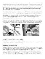
Page 12: ...are not to crack the insulator Cracked electrodes are not covered under warranty Trim the wire using a wire cutter to the length noted previously Install the electrode and note the position of tip of the wire with respect to the surface of the burner Trim as needed to provide a 3 16 1 4 gap It is OK to bend the wire a bit as needed to center the tip of the electrode Fig 18 and 19 show typical inst...

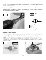
Page 13: ...emale NPT fitting place the o ring washer and adapter bushing onto the sensor as shown in Fig 22 Place 4 5 turns of quality Teflon tape not included to the external NPT threads of the bushing Do not use tape on the sensor threads Then thread the assembly into the fitting Caution Once installed the bushing CANNOT be removed DO NOT over tighten Use a wrench to tighten the sensor and thread it into t...

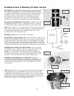
Page 14: ...r mash tun to the inlet of the pump Install a flow control valve after the pump Then plumb through the sensor and lastly back to the TOP of the mash bed Note it is also acceptable to switch the order of the flow control valve and the sensor Installing the sensor in your own system locate the sensor according to the schematic in Fig 25 A close up of the sensor installed in a pipe T not included but...

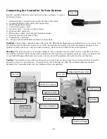
Page 15: ...this power will cause permanent damage to the ignition system and is not covered under warranty Never exceed 30 PSI on the solenoid valve Warning The ignition system uses high voltage to create a spark Do not power up the controller and leave the selector switch in Reset mode until connections of the ground and ignition wires are made or shock could occur ALWAYS place the black vinyl cover over th...

Page 16: ...ning If you are unable to ignite after 10 sec turn the selector switch to RESET immediately This will deactivate the gas valve and ignition sequence Check fuel tank level and that all gas valves and regulators are on Check that the solenoid valve is installed in the correct direction and that the ignition and ground wires are properly installed At this time you can return the selector switch back ...

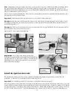
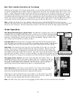
Page 17: ... the flow meter is equipped with a low flow switch and alarm horn that will notify you in advance that your flow is dropping and your mash is beginning to stick Simply slide the switch assembly up or down to the desired low flow setting Important It is possible for bits of grain to become lodged in the valve or in the flow meter This may give a false indication that the mash is sticking Simply ope...

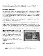
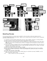
Page 18: ...djust the flow to your desired setting using the handle on the 3 way valve or your flow control valve to throttle it back if needed NEVER throttle the flow to the INLET of the pump ALWAYS on the OUTLET of the pump 5 Place all controller mode selector switches to RESET 6 Turn on the controllers and enter the desired strike water and HLT temperature into the controller 7 Place both controllers in AU...

Page 19: ... need to be sanitized it DOES need to be clean We recommend recirculating PBW Powdered Brewery Wash and then StarSan through your system immediately after each use Simply use a bottling bucket filled with PBW elevate it above your pump and connect with a hose to the inlet of the pump Place the outlet hose return hose to your mash tun in the top of the bucket Open the valves and start the pump If u...

Page 20: ...ons and your fastest way to resolve your issues if the chart below does not resolve your problem Your retailer will contact Blichmann Engineering if they are unable to resolve your issues Display flashing Press enter key to accept temperature setting If flashing does not stop cycle power on front of controller If this recurs contact your retailer Overshoot Increase flow and or decrease heat input ...

Page 21: ... are open Check that mash is not stuck compacted See below Check that all hoses downstream of the pump are empty Install a bleed valve after the pump to vent air and allow the pump to fill with liquid For Tower users the sample port can be used Mash is sticking Reduce flow rate Ensure you have done a dough in WITHOUT the pump on to allow air to purge from the grain bed Check that grain crush is no...

Page 22: ... will be the responsibility of the customer Resolution of warranty claims will be by repair or replacement and will be the decision solely of Blichmann Engineeringtm Shipping costs for warrantee returns are covered only for the contiguous United States User is responsible for packaging costs and shipping damage if not returned in original packing Approval for return must be provided by Blichmann E...

Reviews: