6
Optional Tower Stand
1 – Tower assembly (enclosure, plumbing manifold, valves, flow meter)
1 – Grommet – pump wire, installed McMaster 9600K33
1 – Grommet – flow switch wire, installed McMaster 9600K15
2 – Legs, LH (TOP-003-03-LEGSET, one RH and one LH per set)
2 – Legs, RH
4 – Leveling feet BE5000012-00
2 – Leg stiffening plates (3” X 2-1/4” plate with 2 holes)
1 – Pump mounting bracket (replacement order: aTopTier_Pump_Bkt Includes plate, drip shield, hardware)
1 – Pump drip shield
8 – ¼-20 X3/4” L hex bolts, nuts and washers
2 – 5/16 X 3/4” hex bolts
4 - #10-24 X 3/8” L pan head screws
1 – Hose assembly (silicone hose and 2 QuickConnector aQC_12_S)
1 – 3/8” 90 deg QuickConnector fitting (aQC_38_EL)
1 – 1/2” 90 deg QuickConnector fitting (aQC_12_EL)
1 – Pump – March 815 (if ordered with Tower)
Optional Dual Controller Mounting Plate (reqd for mounting two controllers onto the tower)
1 - Plate (model aCon_plate_TOP)
4 - #10-24 X 3/8” long pan head screws
Assembling the Tower
Prepare a work area with a soft pad to protect the tower enclosure from getting scratched during assembly.
WARNING!
–
Make sure that the tower is NOT plugged in until you have fully completed the assembly!
Electric shock is possible while wiring the pump!
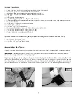
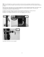
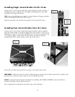
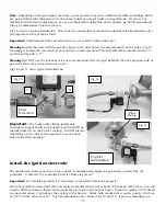
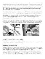
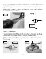
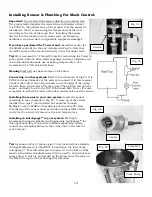
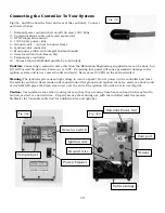
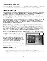
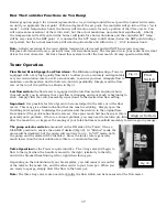
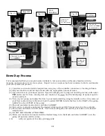
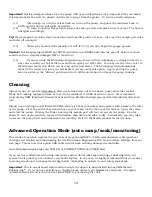
Begin by unpacking and spreading out the parts. Install the legs to the bottom of the tower using the ¼-20
bolts, nuts and washers as shown in Fig 1a and 1b. Please note that there are two LH legs, and two RH legs.
One of each leg is installed on each side of the enclosure. Make sure to install the rectangular leg stiffening
plate on the INSIDE of the enclosure. Next thread a leveling foot into the end of each leg as shown in Fig 3.
Fig 1b
Fig 1a


