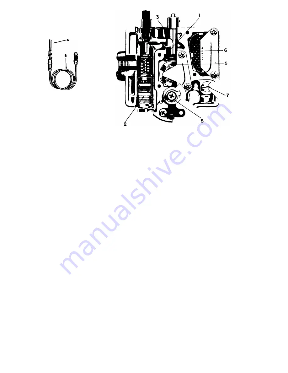
THERMO-MAGNETIC AUTOMATIC PILOT
A tubular thermocouple of a small rod welded within a tube of heat resistant metal (A) bathed by the pilot flame generates an electric current.
Carried through heavy tubular copper conductor (B), the current energizes a heavy electro-magnet (2) capable of holding the valve mechanism
(5) in the operating position as long as the pilot flame remains lighted. Within a minute after pilot flame failure (perhaps caused by a draft,
clogging or "no gas") the electro-magnet releases with a positive snap action shutting off the main burner and pilot gas supply. THERMOSTAT
WITH AUTO SAFETY PILOT IS AN OPTIONAL FEATURE
PROCEDURE FOR LIGHTING OR RELIGHTING:
1. Turn GAS COCK HANDLE to "off" position and DIAL ASSEMBLY to lowest temperature position.
2. Wait sufficient length of time to allow gas which may have accumulated in burner compartment to escape.
3. Turn GAS COCK HANDLE to "Pilot" position.
4. Fully depress SET BUTTON, and light pilot burner. (Adjust, if necessary, as noted under "Pilot Burner Adjustment".)
5. Allow pilot to burn approximately 1/2 minute before releasing SET BUTTON. If pilot does not remain ignited, repeat operation allowing longer
period before releasing SET BUTTON.
6. Turn GAS COCK HANDLE to "on" position and turn DIAL ASSEMBLY to desired position. The main burner will then ignite.
PILOT BURNER ADJUSTMENT:
1. Remove pilot adjustment cap. Adjust pilot key, allowing flame to completely envelop the end 3/8" of the Thermocouple.
2. Adjust pilot burner air shutter (if provided) to obtain a soft blue flame.
MAIN BURNER ADJUSTMENT (Gas Input):
1. To adjust main burner flame, turn screw under GAS COCK HANDLE in either direction to regulate flow of gas to main burner.
To Recalibrate Thermostat:
a. Allow heater to set without the burner on for at least 30 minutes to allow the water temperature within the tank to reach its equilibrium point.
b. Turn the DIAL ASSEMBLY until the main burner ignites.
c. Slowly turn the DIAL ASSEMBLY until the main burner is extinguished.
d. Place a Thermometer in the hot water flowing from the nearest faucet
e. If the DIAL ASSEMBLY setting is within 10° of the water temperature, recalibration is not necessary.
f. If the temperature variation is greater than 10°, recalibration may be effected by adherence to the following steps;
g. Remove DIAL ASSEMBLY GAS COCK HANDLE and ORNAMENTAL COVER, (to remove Ornamental Cover, unsnap at base, lift out and up),
and loosen (do not remove) screw. Hold STOP while screw is loosened, taking care not to move TEMPERATURE ADJUSTING SCREW.
h. Hold TEMPERATURE ADJUSTING SCREW and turn STOP until water temperature setting coordinates with that of the thermometer. i. Hold
TEMPERATURE ADJUSTING SCREW and STOP and tighten screw. j. Replace ORNAMENTAL COVER, GAS COCK HANDLE, DIAL
ASSEMBLY.
Thermocouple Connection
Poor contact between the Thermocouple Lead and the Magnet Assembly may cause the Valve to be inoperative even when the pilot is in proper
adjustment and position; if so, the contact points should be cleaned and tightened. This is accomplished by removing the Thermocouple and care
fully cleaning the parts that make contact with the Magnet Assembly.
CAUTION:
When reassembling and tightening the Thermocouple Nut, only a small (3 or 4 inch) wrench is necessary. Run nut down as far as
possible with the fingers. Set lock washer by making an additional 1/4 to 1/2 turn with wrench.
7 LSQ


