PKP2600SI_CANopenUM_REV1.1
10/28
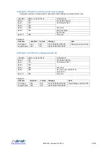
17.Object 2002h: Digital output module.
This module sets and reads the LED Blink States.
Each bit position represents the corresponding LED. A one indicates the LED is blinking a zero
indicates the LED is not blinking. If the blink message is sent when the LED is already ON, the LED
blinks in alternative mode.
a)
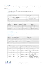
Set LED blink
•
PKP 2600SI
Identifier
600h + current CAN ID
Default 615h
Byte 0
2Bh
Set Device Register
Byte 1
02h
CAN Object 2002h
Byte 2
20h
Byte 3
XXh
XX: Sub index
01h: Red Led
02h: Green Led
03h: Blue Led
Byte 4
YYh
L8 L7 L6 L5 L4 L3 L2 L1 LED position
Byte 5
ZZh
00 00 00 00 L12 L11 L10 L9 LED position
Byte 6,7
00h
Not used
Examples:
Direction
Identifier
Format
Message
Data
To Keypad
615
Std
2B 02 20 01 04 00 00 00
Set red LED #3 blink
Keypad Reply
595
Std
60 02 20 01 00 00 00 00
To Keypad
615
Std
2B 02 20 03 00 02 00 00
Set blue LED #10 blink
Keypad Reply
595
Std
60 02 20 03 00 00 00 00
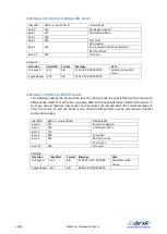
b)
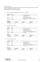
Read LED blink
•
PKP 2600SI
Identifier
600h + current CAN ID
Default 615h
Byte 0
40h
Read Device Register
Byte 1
02h
CAN Object 2002h
Byte 2
20h
Byte 3
XXh
XX: Sub index
01h: Red Led
02h: Green Led
03h: Blue Led
Byte 4,7
00h
Not used
Examples:
Direction
Identifier Format
Message
Data
To Keypad
615
Std
40 02 20 01 00 00 00 00
Read red LED blink
Keypad Reply
595
Std
4B 02 20 01 FF 0F 00 00
All red LED blink
To Keypad
615
Std
40 02 20 02 00 00 00 00
Read green LED blink
Keypad Reply
595
Std
4B 02 20 02 01 00 00 00
Only green LED #1 blinks
To Keypad
615
Std
40 02 20 03 00 00 00 00
Read blue LED blink
Keypad Reply
595
Std
4B 02 20 03 00 08 00 00
Blue LED #12 blinks


