7/31
PowerTrackCANopenUM_REV1.4
10.
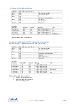
Set LED on message
Identifier
215h (200 + current CAN ID)
Default 215h
Byte 0
LG8 LG7 LG6 LG5 - LG4 LG3 LG2 LG1
KEY LED green
Byte 1
LG16 LG15 LG14 LG13 – LG12 LG11 LG10 LG9
KEY LED green
Byte 2
LR4 LR3 LR2 LR1– 0 0 LG18 LG17
KEY LED green and red
Byte 3
LR12 LR11 LR10 LR9 – LR8 LR7 LR6 LR5
KEY LED red
Byte 4
0 0 LR18 LR17 – LR16 LR15 LR14 LR13
KEY LED red
Byte 5
LR26 LR25 LR24 LR23 – LR22 LR21 LR20 LR19
RING LED red
Byte6
LG26 LG25 LG24 LG23 – LG22 LG21 LG20 LG19
RING LED green
Byte 7
LB26 LB25 LB24 LB23 – LB22 LB21 LB20 LB19
RING LED blue
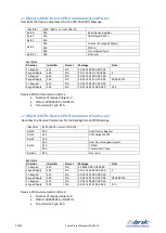
Examples:
Direction
Identifier
Format
Data
LED
To Keypad
215
Std
00 00 00 00 00 00 00 00
Turn off all the LED
To Keypad
215
Std
01 00 00 00 00 00 00 00
Turn on LED LG1
To Keypad
215
Std
42 00 00 00 00 00 00 00
Turn on LED LG2 and LG7
To Keypad
215
Std
00 00 01 00 00 00 00 00
Turn on LED LG17
To Keypad
215
Std
00 10 00 00 00 00 00 00
Turn on LED LG13
To Keypad
215
Std
00 20 00 08 00 00 00 00
Turn on LED LG14 and LR8
Set LED state message is mapped into:
-
Object 2001 sub 1 and sub 2
-
Object 2002 sub 1, sub 2 and sub 3
Refer to the applicable objects for more details.
11.
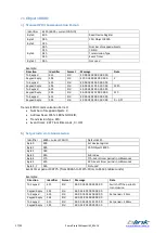
Set LED blink message
Note: if the blink message is sent when the LED is already on, the LED blinks in alternate mode.
Identifier
315h (300 + current CAN ID)
Default 315h
Byte 0
LG8 LG7 LG6 LG5 - LG4 LG3 LG2 LG1
KEY LED green
Byte 1
LG16 LG15 LG14 LG13 – LG12 LG11 LG10 LG9
KEY LED green
Byte 2
LR4 LR3 LR2 LR1– 0 0 LG18 LG17
KEY LED green and red
Byte 3
LR12 LR11 LR10 LR9 – LR8 LR7 LR6 LR5
KEY LED red
Byte 4
0 0 LR18 LR17 – LR16 LR15 LR14 LR13
KEY LED red
Byte 5
LR26 LR25 LR24 LR23 – LR22 LR21 LR20 LR19
RING LED red
Byte6
LG26 LG25 LG24 LG23 – LG22 LG21 LG20 LG19
RING LED green
Byte 7
LB26 LB25 LB24 LB23 – LB22 LB21 LB20 LB19
RING LED blue
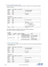
Examples:
Direction
Identifier
Format
Data
LED
To Keypad
315
Std
00 00 00 00 00 00 00 00
Turn off all the BLINK LED
To Keypad
315
Std
01 00 00 00 00 00 00 00
Turn on BLINK LED LG1
To Keypad
315
Std
42 00 00 00 00 00 00 00
Turn on BLINK LED LG2 and
LG7
To Keypad
315
Std
00 00 01 00 00 00 00 00
Turn on BLINK LED LG17
To Keypad
315
Std
00 10 00 00 00 00 00 00
Turn on BLINK LED LG13
To Keypad
315
Std
00 20 00 08 00 00 00 00
Turn on BLINK LED LG14 and
LR8
Set LED Blink message is mapped into:
-
Object 2001 sub 3 and sub 4
-
Object 2002 sub 4, sub 5 and sub 6
Refer to the applicable objects for more details.


