
5
f e a t u r e s a n d s p e c i f i c a t i o n s
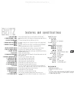
Adjustable bass boost
and bass frequency
(25Hz- 250Hz)
Quality factor
Selectable crossover
frequency
-
Subwoofer (Low Pass)
- Mid high pass
- Mid low pass
- High Pass
Power supply
Input impedance
S/N ratio
Slope Rate
Max output signal level
Channel separation
Distortion
Dimensions
20-2 (Variable)
40Hz-400Hz
40Hz-800Hz
2KHz-7KHz
40Hz-8KHz
10-16V DC, negative ground
10K Ohm
more than 85dB
12dB/Octave
7.0V RMS
60dB
less than 0.05%
1.8"H x 9.3"W x 6.4"D
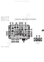
1. INPUT LEVEL CONTROL
2. SUBWOOFER FREQUENCY CONTROL
3. BASS BOOST FREQUENCY LEVEL
CONTROLS
4. MID RANGE / HIGH PASS FREQUENCY
SELECTOR
5. MID RANGE / LOW PASS FREQUENCY
SELECTOR
6. HIGH PASS FREQUENCY SELECTOR
7. HIGH PASS / BAND PASS SELECTOR
8. FREQUENCY MULTIPLIER
9. IN / OUT SWITCH
10. SUBWOOFER SELECTABLE PHASE
SHIFTER
11. SUBWOOFER STEREO/MONO SELECTOR
12. SUBWOOFER GAIN CONTROL
13. MID RANGE GAIN CONTROL
14. HIGH PASS GAIN CONTROL
15. REAR CHANNEL INPUT PORT
16. FRONT CHANNEL INPUT PORT
17. IN / OUT PORT
18. SUBWOOFER OUTPUT PORT
19. MID RANGE OUTPUT PORT
20. HIGH PASS OUTPUT PORT
21. POWER TERMINALS
22. LED POWER ON INDICATOR
Turning this control to adjust the input sensitivity of the set to match the radio's output.
For selection of the Low-pass crossover frequency for the subwoofer channel between 40Hz and
400Hz.
For increasing the bass boost level up to +12dB from 25Hz to 250Hz.
By turning the selector you can choose a high pass crossover point for the mid output between
40Hz-800Hz
By turning the selector you can choose a low pass crossover point for the mid output between
2-7KHz
This adjustment only applies when switch number 7 is placed on BAND PASS.
By turning the selector you can choose the high-pass crossover points from 40Hz-8kHz.
Positioning this switch is at high pass mode, the low pass filter cannot be used.
Positioning this switch at the"10" changes crossover points from 40Hz-800Hz to 400Hz-8kHz for
high frequency high channel drivers.
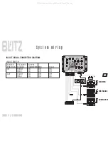
See page 6 (signal connection diagram)
Allows you to change the phase of your subwoofer 0 or 180 degrees to help compensate for timing
differences between drivers.
For selection of stereo or mono mode subwoofer output.
For adjusting the subwoofer channel output signal level.
For adjusting the mid range channel output signal level.
For adjusting the high pass channel output signal level.
To be connected to the rear channel outputs of the source unit.
To be connected to the front channel outputs of the source unit.
You can use this connection if you have a third pre-amp audio source for the subwoofer in or
connect two or more BZX-7 modules out to create a system with an unlimited number of amplifiers.
To be connected to the subwoofer channel amplifier left/right inputs.
To be connected to the rear channel amplifier input.
To be connected to the front channel amplifier left/right inputs.
Use these connectors to deliver power, ground and remote turn-on control to the unit.
The LED indicator lights up when the internal switching power supply is activated and the unit
is operational.
REMOTE CONTROL UNIT
1 SUBWOOFER LEVEL CONTROL
This control sets the subwoofer level control.
2 Q SELECT
This control will narrow or widen the boost frequency bandwidth (Q=factor) being
sent to the amplifier for each band from Q=20(Narrow bandwidth, steep slope) to
Q=2 (Wide bandwidth, gentle slopes).
All manuals and user guides at all-guides.com