background image


3. 

The

 lift 

  7 

117127 

● 07/2011 

3.3  Safety mechanisms 


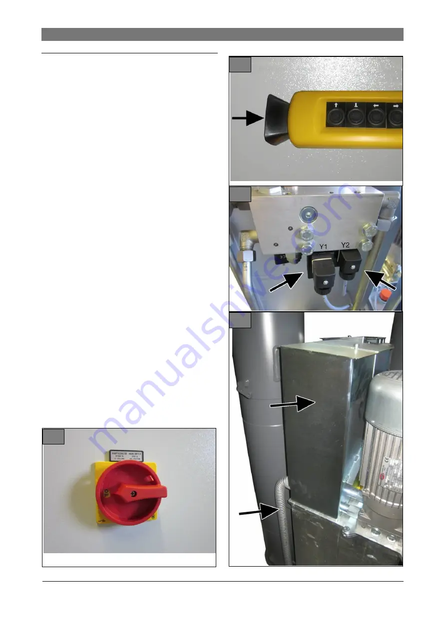
Illustrations 7 ... 10: Safety mechanisms 


Electric 


Emergency stop switch on control panel and  
control cabinet 


Main switch, lockable 


Dead man’s control for lifting and lowering 


Synchronous run control ± 45 mm 


Synchronous run monitoring < 100 mm 


Electronic controls with second CPU for monitor-
ing 


Safety stop during lowering 500 mm above floor 
level 


Acoustic alarm during lowering 


Hydraulic 


Safety cylinder with 2 independent hydraulic cir-
cuits 


Overload pressure control valve 


Seat valve in case of drive failure 


Flow control valve for speed limitation during 
lowering  


Mechanical 


Protective housing for leakage detection 


7


8


9


10


Summary of Contents for DUPLEX S2

Page 1: ...sss1 Foreword Operating instructions DUPLEX S2 In ground truck lift Type Serial number Date Rev A 117127 07 2011 ...

Page 2: ......

Page 3: ...mplied with according to Annex I no 1 5 1 machine directive 2006 42 EG Applied harmonized standards EN 1493 1998 A1 2008 Vehicle lifts EN ISO 12100 1 2003 Safety of machinery Basic concepts EN ISO 12100 2 2003 Safety of machinery Basic concepts EN 60204 1 2006 7 2007 Electrical equipment of machines EN 349 1993 A1 2008 Safety of machinery Minimum gaps EN ISO 13850 2008 Safety of machinery Emergenc...

Page 4: ......

Page 5: ...p points on vehicle 13 5 7 Select pick up equipment 13 5 8 Attach lifting cylinders to vehicle 13 5 9 Activate synchronous operation 13 5 10 Lifting lowering 13 5 11 Drive vehicle off the lift 14 5 12 Switch off equipment 14 5 13 Operation without controls FOR 14 5 14 Store distance between axles option AAV 15 6 Malfunctions 16 6 1 Emergency lowering 17 7 Malfunction reports 18 7 1 Malfunction ind...

Page 6: ...scrap 28 ANNEX 29 Inspection book with Master data sheet DUPLEX S2 lift Form Set up protocol Form Handover certificate Form Initial safety check before start up Form Annual safety check Form Special safety check Maintenance report Diagrams spare part lists additional instruc tions Electric diagram see control cabinet Hydraulics diagram Spare part lists ...

Page 7: ...fe op eration is guaranteed at all times and that the follow ing specifications are observed and regularly checked The operating staff must be qualified trained and experienced The operating staff must know the occupational health and safety regulations and must be trained in operating the lift The operating staff must have read understood and signed the safety precautions A supervisor must be app...

Page 8: ...cially aware of safety and danger Observe the occupa tional health and safety regulations for your country Danger to life risk of injury Immediate danger for life and per sonal injuries Non observance can lead to death or severe injuries Danger to life risk of injury Possible danger for life and personal injuries Non observance can lead to severe or life threatening injuries Risk of injury Possibl...

Page 9: ...osive areas 3 The lift 3 1 Mode of operation The lift is used to lift heavy vehicles for mainte nance cleaning or repair to optimum working height Operation is carried out with a mobile control panel Lifting and lowering the vehicle is carried out in jog mode Electronic controls ensure level lifting of the ve hicle The lifting cylinders are movable in vehicle longi tudinal direction to adjust for ...

Page 10: ...with 2 lifting cylinders 1 Lifting cylinder fixed 2 Cross member 3 Load bearing equipment 4 Control panel mobile 5 Control cabinet with controls 6 Type plate 7 Cross member 8 Lifting cylinder movable 9 Load bearing equipment 10 Cover 11 Hydraulic unit 12 Maintenance door 3 The lift 1 ...

Page 11: ...lic cylinder Illustration 3 Nominal load per lifting cylinder Maximum 15 t minimum 0 8 t Load distribution in or against driving direction maximum 2 1 Minimum distance between lifting cylinders in driving direction 1 5 m Illustration 4 Flexcover Permissible traversing load maximum 3 t per wheel Illustration 5 Metal cover Permissible traversing load maximum 0 3 t per wheel 2 3 4 5 ...

Page 12: ...3 The lift 6 117127 07 2011 3 2 Workplace danger zones Illustration 6 Work and danger zones 1 Operating position 2 Working area 3 Danger zone 4 Escape route 6 ...

Page 13: ...n control 45 mm Synchronous run monitoring 100 mm Electronic controls with second CPU for monitor ing Safety stop during lowering 500 mm above floor level Acoustic alarm during lowering Hydraulic Safety cylinder with 2 independent hydraulic cir cuits Overload pressure control valve Seat valve in case of drive failure Flow control valve for speed limitation during lowering Mechanical Protective hou...

Page 14: ...3 The lift 8 117127 07 2011 ...

Page 15: ... Manual adjustment of the vehicle position Automatic controls are deactivated Current lift allocation is canceled Control panel 1 is activated Control commands Up and Down apply to activated lifting cylinder For safety reasons a second operator must be called in This person must permanently activate FOR switch and monitor the operator 7 Fault report indicators L1 L4 15 fault reports are allocated ...

Page 16: ... indicator lamp Flashes Selected lifting cylinder loaded Lights up Synchronized operation activated 2 Synchronized operation On Off push button 3 Activate Lifting cylinder switch 4 button Lift 5 button Lower 6 button Drive forward in pit 7 button Drive back in pit 8 Emergency stop button ...

Page 17: ...e vehicle Only lift vehicles on manufacturer approved posi tions No work which affects the stability of the pick up points on the lifted vehicle is permitted 4 4 Lifting lowering Only operate the lift if no persons are at risk No persons are permitted within the load and pick up area during lifting and lowering After lifting just above floor level check that the vehicle is secure Only afterwards l...

Page 18: ...on controls with button 2 5 3 Lift allocation optional Lifts with 4 5 or 6 lifting cylinders can be allocated to individual workplaces a control panel is provided for each workplace 14 1 Allocate lift with selector switch according to Illustration 14 The allocated control panels are activated Different allocation can only be selected with all lifting cylinders unloaded 5 4 Detect vehicle data 1 De...

Page 19: ...ition 3 Lift the vehicle slightly with the Up button until the indicator Illustration 12 pos 1 shows load flashes The lifting cylinder is in position Notes Only lift vehicle at permissible positions according to the manufacturer Check safe positioning after lifting slightly The vehicle must sit free on the load bearing equipment The indicator flashes after the vehicle is lifted approx 5cm Buttons ...

Page 20: ...itch off power supply with main switch Illustration 13 pos 1 OFF position and secure main switch with padlock 5 13 Operation without controls FOR WARNING Danger due to poorly defined re sponsibilities Inform all persons in the lift area that you are manually adjusting the vehicle position All affected vehicles are to be lowered before the adjustment if the lift is allocated to several workplaces A...

Page 21: ...5 6 and 5 7 2 Position and adjust the lifting cylinders precisely under vehicle axles chapter 5 8 3 Select memory preset with rotary switch Nr Distances between axles for up to 9 vehicles can be stored option available for 18 or 27 ve hicles 4 Store distance between axles with key switch SP 5 Enter vehicle type in list Retrieve distance between axles 1 Select desired vehicle type with rotary switc...

Page 22: ...er load completely Cause Lifting cylinder extended more than 300mm Remedy Lower all lifting cylinders under 300mm Cause Error message in controls Remedy Localize and remedy malfunction accord ing to list in chapter 7 then acknowledge error mes sage Contact customer service if necessary Cause Control button is defective Remedy Replace control button Cause Cable damaged Remedy Check cable and contac...

Page 23: ...ontrols 5 Remove external power supply 6 Have malfunction repaired by electrician Lift secured during malfunction Condition cannot be acknowledged 1 Check according to malfunction list in chapter 7 if FOR mode is permissible 2 If permitted lower the vehicle slowly as de scribed in chapter 5 13 Operation without con trols 3 Clear malfunction Contact authorized customer service if necessary Lowering...

Page 24: ...econds 1 Emergency stop or equipment switched off On board 4 LEDs light up red no 2 Motor overload switch has been triggered yes 3 Malfunction on electronics board ADC voltage or CAN bus error no 3 FLASHES Calibration error sensors or flash memory error yes 4 Power output too hot or short circuit no 5 Low oil level yes 6 Cable break for level sensor yes 7 Defective level sensor in oil tank yes 8 D...

Page 25: ...pecifications Prevent environmental hazards Observe environmental disposal regulations chapter 15 2 Avoid contact with or inhaling of toxic substances such as hydraulic oil Wear protective clothing e g goggles protective gloves etc Danger of suffocation in unventilated pit Ventilate pit adequately before start of work Do not work alone in the pit Ensure adequate lighting 8 3 Maintenance schedule C...

Page 26: ...eplace dipstick 5 Calibrate the sensor setting after every interven tion in the hydraulic system chapter 8 13 8 6 Permitted hydraulic oils Important notes Only use hydraulic oil according to DIN 51524 for the hydraulic system Contact us when using hydraulic oil of other manufacturers Oil and lubricants are hazardous to water Always dispose of these substances in an environmental ly friendly manner...

Page 27: ...8 Remove padlock switch on lift 8 8 Tighten mounting screws of cross members and shafts 1 Check tightening torque with torque spanner and re tighten if necessary Bolts on cross member M20 with 560Nm Bolts on shafts M16 with 195Nm Tightening torque for bolts For set screws friction factor 0 125 Dimensions Tightening torque Nm Strength category 8 8 10 9 12 9 M 4 2 8 4 1 4 8 M 5 5 5 8 1 9 5 M 6 9 6 1...

Page 28: ...tions Deactivate and secure lift immediately after detecting malfunctions Rectify malfunctions immediately and ensure trouble free operation 1 Check lift function without load 2 Check full lift function with load 8 12 Check safety cylinders 22 Check safety cylinders annually Strictly observe test interval DANGER Danger to life due to electric shock when working on open control cab inet Only electr...

Page 29: ...Synchronous operation 2 and Back 7 buttons for approx 10 seconds 4 Press and hold Up 4 and Forward 6 buttons for approx 10 seconds 5 Press and hold Down 5 and Back 7 buttons for approx 10 seconds The sensors are now calibrated 8 14 Change hydraulic oil Always change the hydraulic oil for all lifting cyl inders Permitted hydraulic oil Hydraulic oil with viscosity 22 cST 40 and quality HLP DIN51524 ...

Page 30: ...e seal and scraper ring Ø180mm Illustration 25 1 Lower lifting cylinder completely 2 Turn off and secure equipment 3 Detach cross member forklift crane 4 Remove the 8 bolts 1 and detach flange 4 5 Change seal ring 3 and scraper ring 2 6 Replace O ring 5 on flange 7 Attach flange tightening torque bolts Ma 395Nm 8 Attach cross member tightening torque bolts Ma 560Nm Change seal and scraper ring Ø15...

Page 31: ...rage conditions Ambient temperature 5 50 C Relative humidity 30 95 not condensing at 20 C The manufacturer is not responsible for cor rosion damage due to incorrect storage 11 2 Transport DANGER Danger of crushing and shearing off of limbs during offloading due to falling or shifting of the load Do not linger in the vicinity or under suspend ed loads Offload and transport packaging units to instal...

Page 32: ...11 Transport storage 26 117127 07 2011 27 ...

Page 33: ...carried out by an authorized expert ac cording to applicable regulations in your country A main fuse must be connected upstream of the lift Number of lifting cylinders 3 N PE 50Hz 400V Rated power KW Rated cur rent A Main fuse A Con nect ing cable mm2 1 4 5 10 16 5G2 5 2 9 20 35 5G6 3 13 5 30 35 5G10 4 18 40 50 5G10 5 22 5 45 63 5G16 6 27 60 63 5G16 Local conditions apply for selecting the protect...

Page 34: ...s must be complied with chapter 15 2 Environmental hazards must be prevented Equipment components must be disposed of according to your local regulations 15 Disposal 15 1 Packaging materials Do not dispose of with the residual waste The packaging party contains recyclable materials which must not be disposed of with general waste 1 Dispose of packaging materials according to local regulations 15 2...

Page 35: ...2 lift Form Set up protocol Form Handover certificate Form First safety check before start up Form Annual safety check Form Special safety check Maintenance report Diagrams spare part lists Electrical circuit diagram see control cabinet Hydraulic circuit diagram Spare parts lists ...

Page 36: ...gainst regulations and misuse Standing and riding on load and pick up equipment standing or working under the suspended load during lifting and lowering lift installation in explosive areas and lifting of vehicles loaded with hazardous goods is prohibited Supplied pick up equipment axle cross members are not adjusted for specific vehicle types They are part of the basic configuration The lift must...

Page 37: ...ty and safety and was commissioned Installation was carried out by operator competent person The operator verifies the set up of the lift All information in these operating instructions and the inspection book have been read and understood The documentation is available to the operators at all times The competent person verifies the correct lift installation All information in the operating instru...

Page 38: ...ioned The following persons operators were trained after lift installation by a trained manufacturer s or authorized dealer s technician competent person in operating the in ground lift Date Name Signature of operator Date Name Signature of operator Date Name Signature of operator Date Name Signature of operator Date Name Signature operator Date Name Signature competent person Customer service par...

Page 39: ...ft components distortion cracks Condition of lifting cylinder Test screws torque Function safety mechanisms Condition of covers Hydraulic system leak proof Fill level of hydraulic tank Condition of hydraulic hoses Condition of electrical cables Function test loaded lift Safety check carried out Date Company Competent person name address Signature of operator Signature of competent person Faults re...

Page 40: ...ts distortion cracks Condition of lifting cylinder Test screws torque Function safety mechanisms Condition of covers Hydraulic system leak proof Fill level of hydraulic tank Condition of hydraulic hoses Condition of electrical cables Function test with lifted vehicle Safety check carried out Date Company Competent person name address Signature of operator Signature of competent person Faults remed...

Page 41: ...onents distortion cracks Condition of lifting cylinder Test screws torque Function of safety mechanisms Condition of covers Hydraulic system leak proof Fill level of hydraulic tank Condition of hydraulic hoses Condition of electrical cables Function test with lifted vehicle Safety check carried out Date Company Competent person name address Signature operator Signature competent person Faults reme...

Page 42: ...components distortion cracks Condition lifting cylinder Test screws torque Function safety mechanisms Condition covers Hydraulic system leak proof Fill level hydraulic tank Condition hydraulic hoses Condition electric cables Function test with lifted vehicle Safety check carried out Date Company Competent person name address Signature operator Signature competent person Faults remedied on Use diff...

Page 43: ...onents distortion cracks Condition lifting cylinder Test screws torque Function safety mechanisms Condition covers Hydraulic system leak proof Fill level hydraulic tank Condition hydraulic hoses Condition electric cables Function test with lifted vehicle Safety check carried out Date Company Competent person name address Signature operator Signature competent person Faults remedied on Use differen...

Page 44: ...ponents distortion cracks Condition lifting cylinder Test screws torque Function safety mechanisms Condition covers Hydraulic system leak proof Fill level hydraulic tank Condition hydraulic hoses Condition electric cables Function test with lifted vehicle Safety check carried out Date Company Competent person name address Signature operator Signature competent person Faults remedied on Use differe...

Page 45: ...ponents distortion cracks Condition lifting cylinder Test screws torque Function safety mechanisms Condition covers Hydraulic system leak proof Fill level hydraulic tank Condition hydraulic hoses Condition electric cables Function test with lifted vehicle Safety check carried out Date Company Competent person name address Signature operator Signature competent person Faults remedied on Use differe...

Page 46: ...ponents distortion cracks Condition lifting cylinder Test screws torque Function safety mechanisms Condition covers Hydraulic system leak proof Fill level hydraulic tank Condition hydraulic hoses Condition electric cables Function test with lifted vehicle Safety check carried out Date Company Competent person name address Signature operator Signature competent person Faults remedied on Use differe...

Page 47: ...ponents distortion cracks Condition lifting cylinder Test screws torque Function safety mechanisms Condition covers Hydraulic system leak proof Fill level hydraulic tank Condition hydraulic hoses Condition electric cables Function test with lifted vehicle Safety check carried out Date Company Competent person name address Signature operator Signature competent person Faults remedied on Use differe...

Page 48: ...ponents distortion cracks Condition lifting cylinder Test screws torque Function safety mechanisms Condition covers Hydraulic system leak proof Fill level hydraulic tank Condition hydraulic hoses Condition electric cables Function test with lifted vehicle Safety check carried out Date Company Competent person name address Signature operator Signature competent person Faults remedied on Use differe...

Page 49: ...ponents distortion cracks Condition lifting cylinder Test screws torque Function safety mechanisms Condition covers Hydraulic system leak proof Fill level hydraulic tank Condition hydraulic hoses Condition electric cables Function test with lifted vehicle Safety check carried out Date Company Competent person name address Signature operator Signature competent person Faults remedied on Use differe...

Page 50: ...mponents distortion cracks Condition lifting cylinder Test screws torque Function safety mechanisms Condition covers Hydraulic system leak proof Fill level hydraulic tank Condition hydraulic hoses Condition electric cables Function test with lifted vehicle Safety check carried out Date Company Competent person name address Signature operator Signature competent person Faults remedied on Use differ...

Page 51: ...5 117127 07 2011 Maintenance report Always record carried out maintenance work Tick if appropriate Date Maintenance report carried out by monthly annually biannually Keep completed form in inspection book Annex Type Serial number ...

Page 52: ...INSPECTION BOOK DUPLEX S2 46 117127 07 2011 Date Maintenance report carried out by monthly annually biannually ...

Page 53: ...inder 1V1 Lowering brake valve1 1V4 Solenoid valve 1V5 Solenoid valve 1S2 Pressure sensor 1V2 Pressure relief valve 2 Suction valve 1P Geared pump 1M Electric motor 3kw 1S1 Level sensor 1Z1 Intake filter 6 Emergency relief valve 7 Emergency relief valve M MA G1 4 A P T G1 2 ...

Page 54: ...NE ERSATZTEILLISTEN 48 BlitzRotary GmbH Hüfinger Straße 55 D 78199 Bräunlingen Phone 49 771 9233 0 Fax 49 771 9233 99 info blitzrotary com www blitzrotary com 117127 07 11 Technical modifications reserved ...

Reviews: