background image

4

102619  03/13

Operating Instruction

Transport and storage

Transport and storage

2.1  Transport

Danger

Mortal danger caused by incorrect 

transport.

•  Never lift the compressor by the fan 

cover.

•  Only use suitable lifting gear with 

the corresponding weight-bearing 

capacity (for data on weight, please 

refer to chapter “Technical annex”).

•  Fasten and secure the system with 

belts at the corresponding points.

•  Secure swivelling and loose parts.

•  Transport the compressor by means 

of crane hooks, fork-lift truck and 

elevating truck only.

•  Never remain under suspended 

loads.

•  Depressurise the compressor prior 

to any transport.


2.2  Storage

Store the compressor in a dry location protec-

ted against weather influence. Ambient tempe-

rature: -10° C to +50° C.

Please order the BLITZ conservation instruc-

tions in case of storage of over six months.

3 Mounting

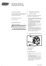
3.1  Mounting conditions

 

Check the compressor for damage during 

transport.

Ambient conditions

Danger

Mortal danger and explosion hazard 

when caustic, inflammable or poisonous 

gases are drawn in.

•  Do not operate the compressor in 

explosive surroundings or in the 

vicinity of open flames and flying 

sparks.


Caution

Wrong mounting will cause damage to 

the compressor.

•  Ensure sufficient ventilation of the 

compressor room.

•  Do not operate the compressor in 

the open.


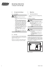
The space between the compressor and the 

wall has to be at least 40 cm (cf. Fig. 2: Locati-

on). The compressor has to be easily accessib-

le from all sides. The ambient temperature has 

to be between 5° C and 40° C.

Fig. 2: Location

> 40 cm

+5°C - +40 °C

Summary of Contents for VERSA DZ Series

Page 1: ...Type Serial number Date Operating Instruction VERSA piston compressors VERSA booster compressors up to 35 bar Rev D 102619 08 2018...

Page 2: ......

Page 3: ...42V GT50V machinery serial number Year of manufacture is complying with all essential requirements of the Machinery Directive 2006 42 EC In addition the partly completed machinery is in conformity wit...

Page 4: ...w 1 Test flange 2 Pressure gauge 3 Pressure switch operating switch 4 Safety valve ultimate pressure 5 Motor 6 Belt guard 7 Suction filter 8 Compressor aggregate 9 Safety valve intermediate pressure 1...

Page 5: ...s proprietor please ensu re that all safety regulations are observed by the operating staff Do not use the compressor as a climbing aid 1 3 Description of symbols and no tes Danger Mortal danger and r...

Page 6: ...protec ted against weather influence Ambient tempe rature 10 C to 50 C Please order the BLITZ conservation instruc tions in case of storage of over six months 3 Mounting 3 1 Mounting conditions Check...

Page 7: ...the electrical power system may be carried out only by adequately trained expert Danger Mortal danger caused by electric volta ge Compressor systems have to be fitted with a power switch or a plug con...

Page 8: ...3 Ph 230V 50Hz 1 Ph Motor out put Nominal motor cur rent Protection star delta start Protection direct start Power supply lead Fuse Power supply lead Maximum system Impedance Zmax kW A A A mm A mm 1 1...

Page 9: ...e additional safe ty instructions in the operating instructions enclosed 4 2 Switching the unit on Check the oil level through the oil level inspection glass and top up the oil if and when necessary c...

Page 10: ...work set the power switch to off or remove the mains plug Use original BLITZ parts and approved operating material only After having completed the servicing work tighten all screws again Depressurise...

Page 11: ...lug Slowly fill new oil cf chapter 5 2 Types of oil until the oil level in oil inspection glass 1 is within the red circle Screw on the oil filler neck 5 4 Draining the condensation water Required onl...

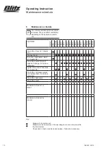
Page 12: ...level cf chapter 5 2 Change the oil Drain the condensation water cf chapter 5 4 Check the suction filter cart ridge and change if and when necessary Tighten the screw connections cf chapter 5 6 Check...

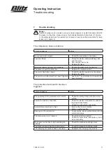
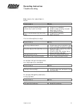
Page 13: ...tric system and the cables Replace the motor The protective motor switch has been triggered See Table The protective motor switch has been triggered The protective motor switch has been triggered Pote...

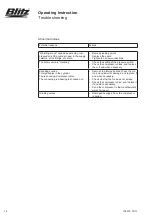
Page 14: ...The cylinder head seal is leaking Tighten the cylinder head screws Replace the cylinder head seal The piston piston rings and the cylinder are worn Check the components Replace the worn parts The pres...

Page 15: ...type of oil cf chapter 5 2 Types of oil and replace if and when necessary The piston rings and the cylinder face are worn Replace the piston rings and the cylinder if and when necessary Check the suc...

Page 16: ...f the pressure switch Check the compressor valves and replace them if and when necessary Knocking sounds Foreign bodies in the cylinder Fan is knocking Compressor valve The connecting rod bearing is k...

Page 17: ......

Page 18: ...GmbH H finger Stra e 55 D 78199 Br unlingen Telefon 49 771 9233 0 Telefax 49 771 9233 99 info blitzrotary com www blitzrotary com 102619 03 13 Technical changes reserved Betriebsanleitung VERSA Kolben...

Reviews: