6
102619 03/13
Operating Instruction
Mounting
Electrical connection conditions
The connection to the electrical power system
may be carried out only by adequately trained
expert.
Caution
Neither over voltage nor under voltage should be exceeded by 10%.
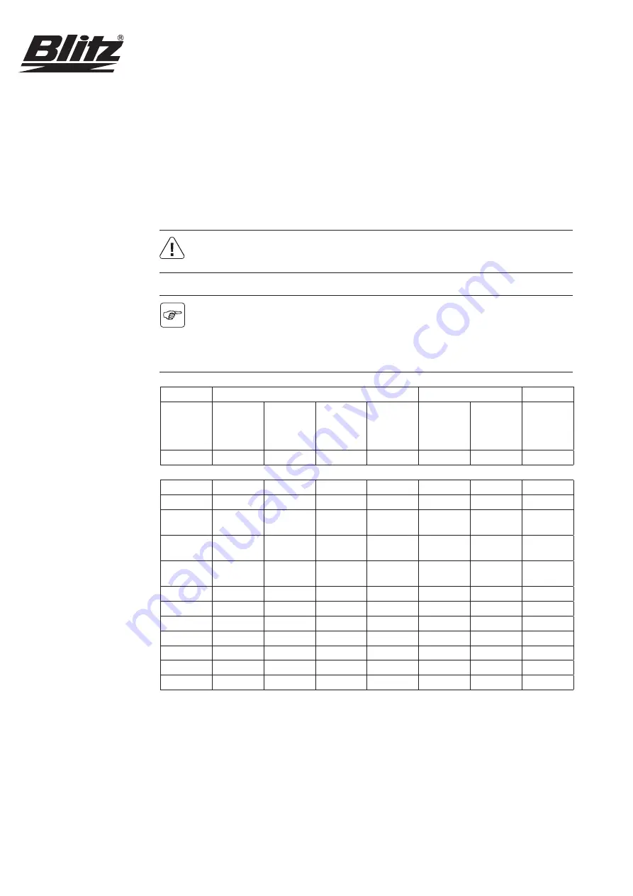
This unit is intended for operation on a power supply network with a maximum system
impedance Zmax at the interconnection point (house service line), which is listed in the
table below in dependence of the performance. The user shall have to ensure that the unit
is operated only on a power supply network which meets these requirements. If and when
necessary, the local power supply company can provide information on the system impe-
dance.
400V-50Hz 3 Ph.
230V-50Hz 1 Ph.
Motor out
-
put
Nominal
motor cur
-
rent
Protection
– star-delta
start
Protection
– direct
start
Power
supply
lead
Fuse
Power
supply
lead
Maximum
system
Impedance
Zmax
kW
A
A
A
mm²
A
mm²
Ω
1,1
2,6
6
4G2,5
16
3G2,5
1,5
3,5/4,1
10
4G2,5
16
3G2,5
-/0,254
2,2
5,0/6,0
16
4G2,5
16
3G2,5
0,127/
0,143
3,0
6,6/8,1
16
4G2,5
0,118/
0,106
4,0
8,5
16
20
4G2,5/
5G2,5
0,072
5,5
11,5
20
5G2,5
0,102
7,5
15,5
25
5G4
11,0
22,5
35
5G6
15,0
30,0
50
5G10
18,5
36,0
50
5G10
22,0
43,0
63
5G16
30,0
58,0
80
5G25
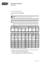
Tab. 1: Characteristic value for the electrical connection
The conductor cross sections mentioned are guideline values for a maximum lead length of 50 m
at a temperature of 30° C. Use a time-lag fuses or “gl fuses”.
• 220 / 240 V systems require a three-core 1P/N/PE cable.
• 380 / 400 V systems require a four-core 3P/PE cable for direct start.
• 380 / 400 V systems require a five-core 3P/N/PE cable for star-delta start.


