Lit. No. B64092, Rev. 09
14
April 15, 2021
MOLDBOARD & A-FRAME ASSEMBLY – 810TR, 8100TR & 8611TR MODELS
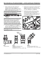
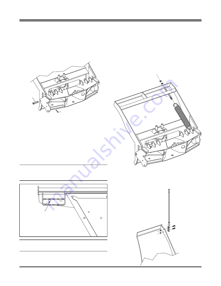
5. Position the pivot beam between the two
support ribs until the connecting points on the
beam align with those on the snowplow. Insert
one 3/4" x 3" clevis pin (
B50069
) through
each mounting hole and secure them with
1/4" x 1-1/2" cotter pin (
90601
).
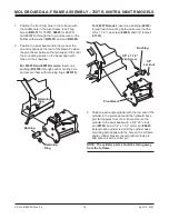
6. Position each angle cylinder with the rod
end of the cylinder in the pivot beam and
the hydraulic hose port facing away from
the A-frame. Secure the cylinder to the pivot
beam with a 3/4" x 5" clevis pin (
95739
) and a
1/4" x 1-1/2" cotter pin (
90601
). Extend each
cylinder rod until the cylinder base mounting hole
aligns with the hole on the A-frame angle cylinder
bracket. Insert another clevis pin and secure it
with a cotter pin.
NOTE: Be sure to use the proper mounting point
when replacing or installing cylinders on 8611TR
models.
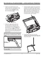
NOTE: The cylinder ports should be facing away
from the A-frame.
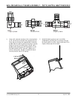
7. Hook each extension spring to the receiving holes
on the pivot beam and attach the opposite end of
the spring to its respective spade bolts. Install the
spade bolts through the extension spring mounting
angle on the top rear of the blade. Secure each
spade bolt by placing one 5/8"
fl
at washer on the
bolt and thread one 5/8" locknut. Tighten each
locknut until a piece of paper can pass between
the third and fourth coils on the spring.
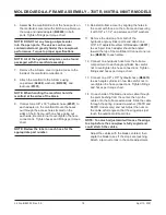
8. Install the blade guides at each end of the
moldboard. Insert the cap screw through the holes
at the top of the wing reinforcement rib. Tighten all
screws with locknuts.
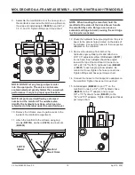
8611 Uses
Outer Holes
Clevis
Pin
Cotter Pin
Summary of Contents for 760TR
Page 2: ......


